Automotive Gauge Cluster Design
Aug 2019 - Dec 2019

Overview
A standalone automotive gauge cluster built around an embedded microcontroller platform. The system integrates a real vehicle gauge cluster with custom control inputs, enabling users to simulate and interact with dashboard functionality through multiple operating modes and real-time feedback.
-
Mechanical:
Led overall system design and enclosure layout
Designed and detailed custom sheet metal enclosure in SOLIDWORKS using sheet metal features
Generated 3D models and flat patterns for fabrication
Defined component placement for accessibility, wiring, and system integration
Electrical:
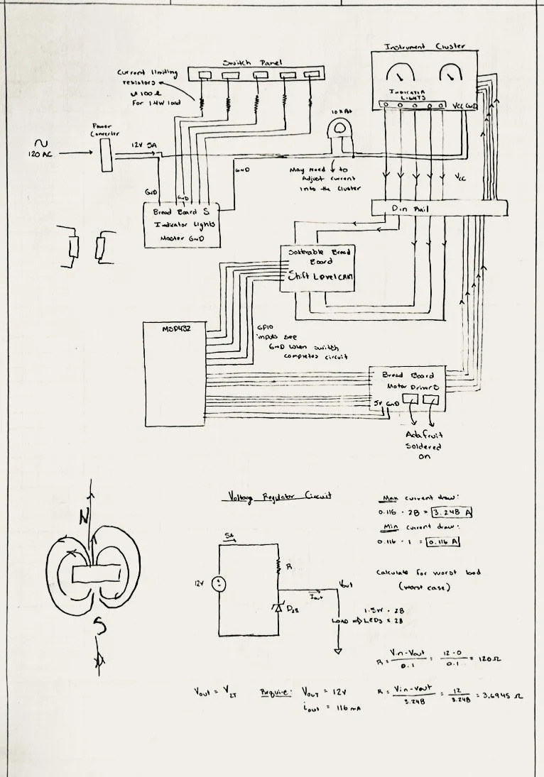
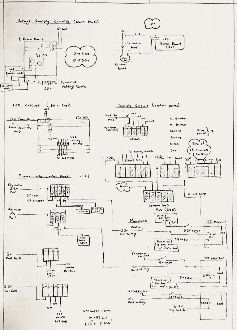
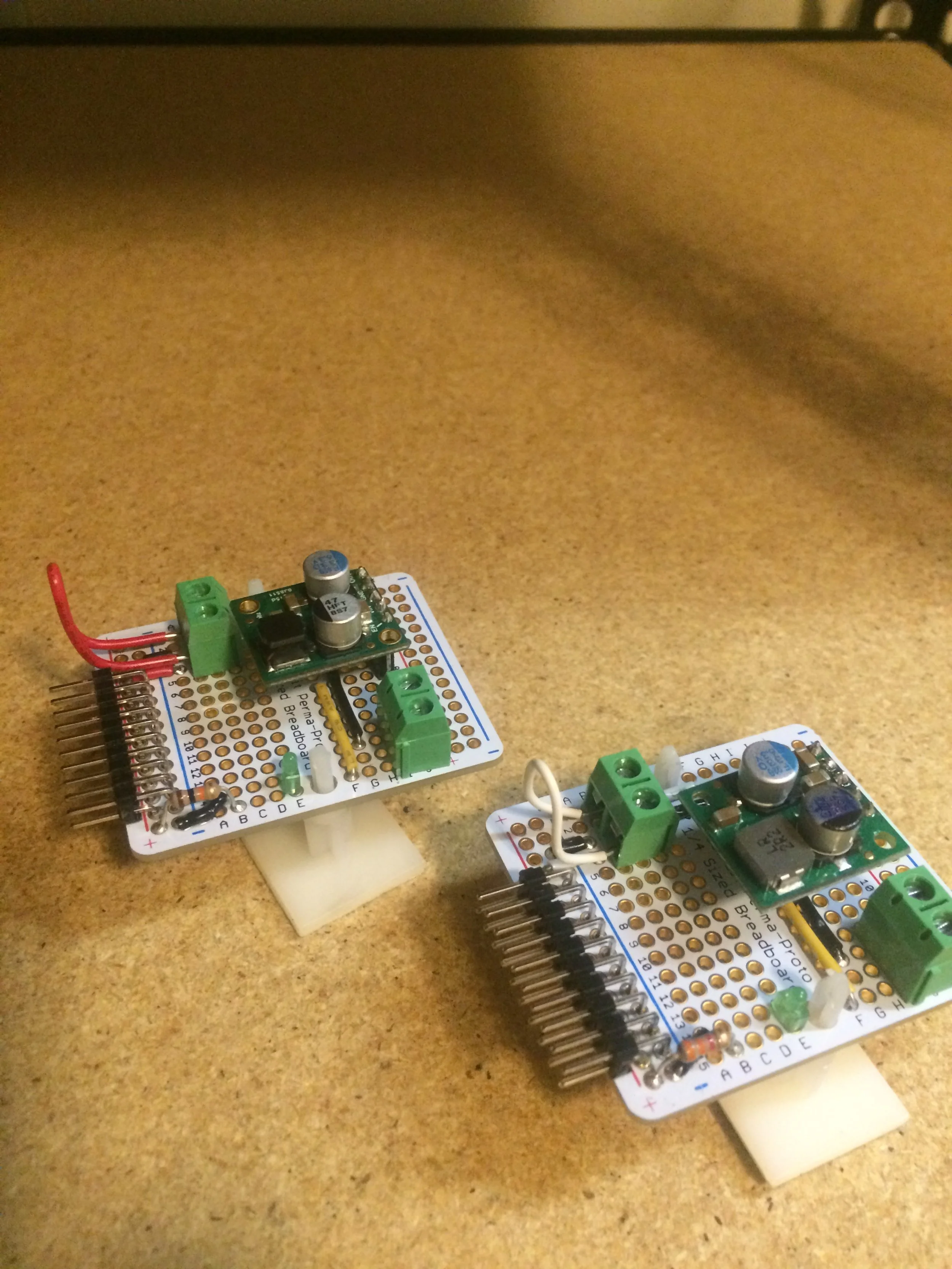
Designed and implemented multi-voltage power system (120VAC → 12VDC → 5VDC / 3.3VDC)
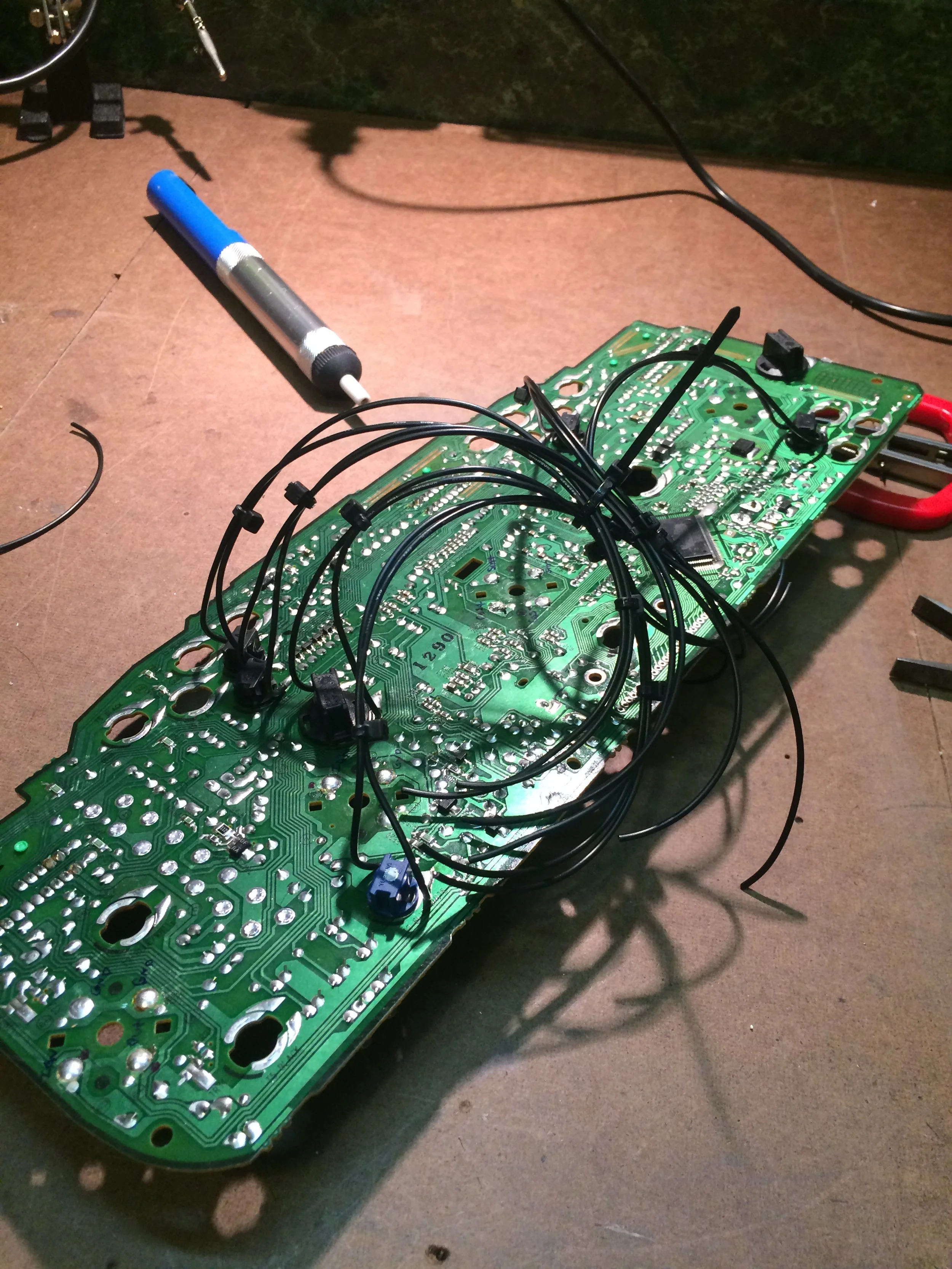
Integrated automotive gauge cluster requiring 12V supply alongside low-voltage control electronics
Routed power and signal wiring with isolation and protection considerations
Built custom wiring harnesses for system-wide integration
Performed soldering, connectorization, and structured cable management
Verified system voltages using onboard measurement and diagnostic indicators
Embedded / System Integration:
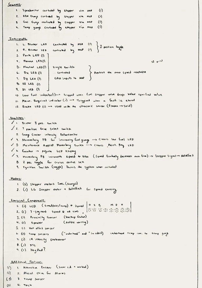
Integrated MSP432 microcontroller with real-time clock, stepper motors, and user inputs
Implemented control of automotive gauge cluster using 12V interface alongside low-voltage logic
Defined hardware architecture and signal flow between subsystems
Coordinated interaction between control inputs, display elements, and system modes
Developed and validated system functionality across multiple operating modes
Production:
Coordinated laser cutting and press brake forming of sheet metal enclosure
Led full system assembly, including mechanical, electrical, and final integration
Collaborated with teammate on project documentation and reporting
-
Design and build an embedded system that simulates an automotive gauge cluster using a microcontroller-based platform.
This project focused on translating system requirements into a functional embedded solution, integrating real-time inputs, sensor data, and user controls into a cohesive dashboard interface.
The system was built around a Texas Instruments MSP432 microcontroller and interfaced with a real automotive gauge cluster sourced from a production vehicle. The design incorporated a real-time clock, analog and digital inputs, stepper motor control, and a display interface to replicate and control dashboard functionality.
The goal was to develop a working prototype that demonstrated reliable system integration, real-time responsiveness, and usability across multiple hardware and software components.
-
Challenges:
Managing scope and complexity while integrating multiple hardware subsystems (gauge cluster, sensors, display, and control inputs)
Time-intensive wiring, harnessing, and physical integration of components within a custom enclosure
Balancing system functionality with project timeline constraints
Outcomes:
Delivered a functional embedded system integrating real automotive hardware with microcontroller-based control
Successfully demonstrated core system behavior and hardware-software interaction
Identified the importance of prioritizing core requirements and managing scope to ensure complete and timely delivery
Explore This Project
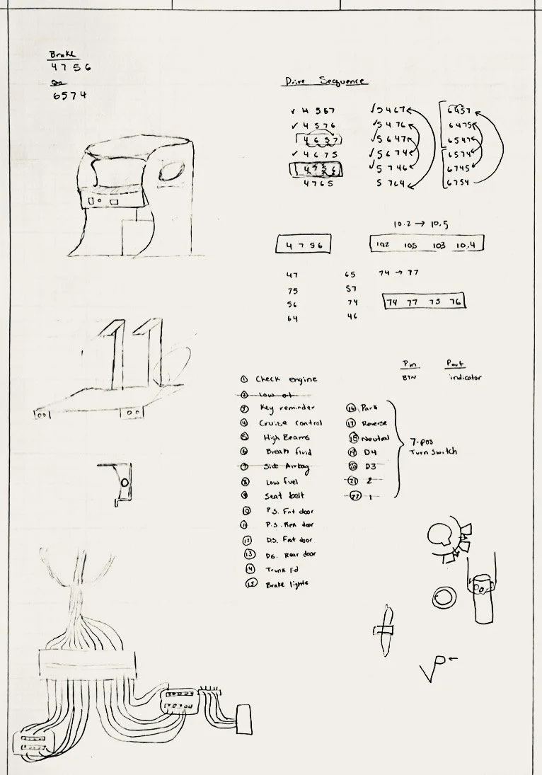
Ideation
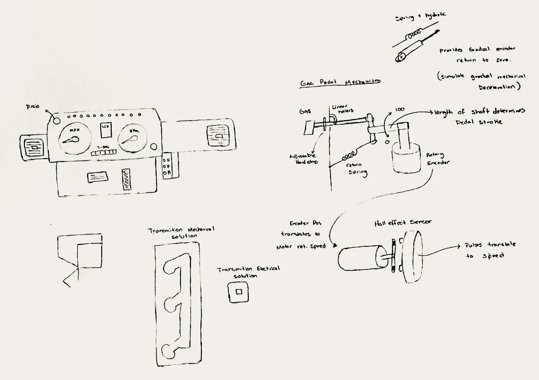
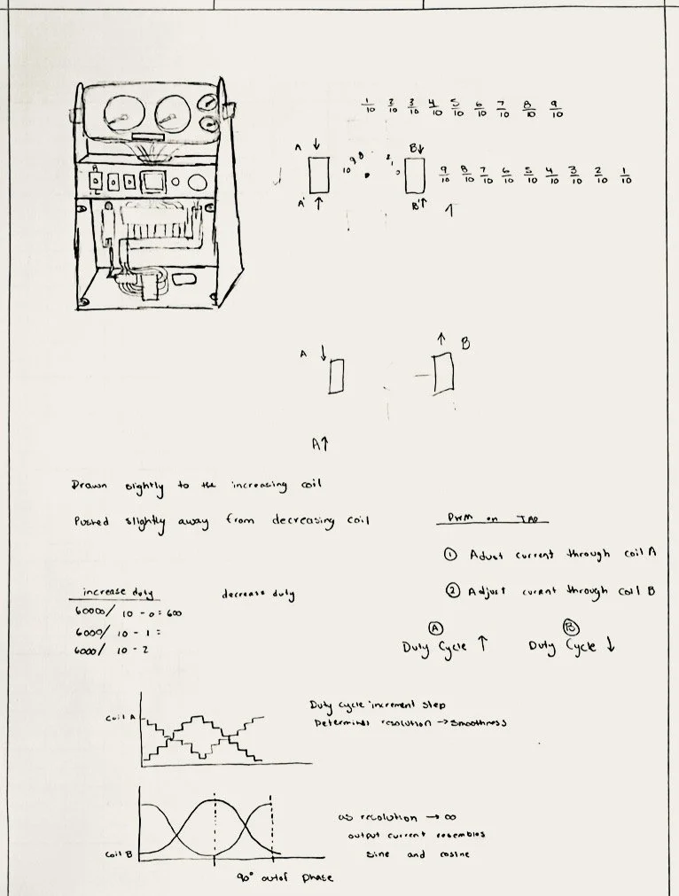
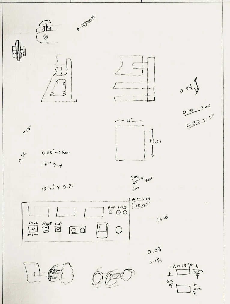
Early-stage sketches were used to explore system architecture, component integration, and enclosure design concepts. This included mapping signal flow between the microcontroller, sensors, and gauge cluster, as well as evaluating control inputs, wiring strategies, and physical layout constraints. Initial concepts were iterated to validate feasibility before moving into implementation.
Software Design
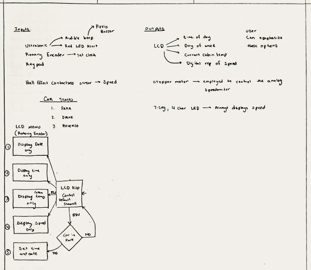
The system was implemented in C using a state machine architecture, where each state represented a different drive mode. A multi-position selector switch acted as the primary input, determining the active state and available system functionality.
Within each mode, the software controlled access to specific features and managed interactions between user inputs, display elements, and system outputs. Transitions between states were driven by switch position and user inputs, enabling structured and predictable system behavior.
Flowcharts were used to design and visualize state transitions, control logic, and user interaction within each operating mode.


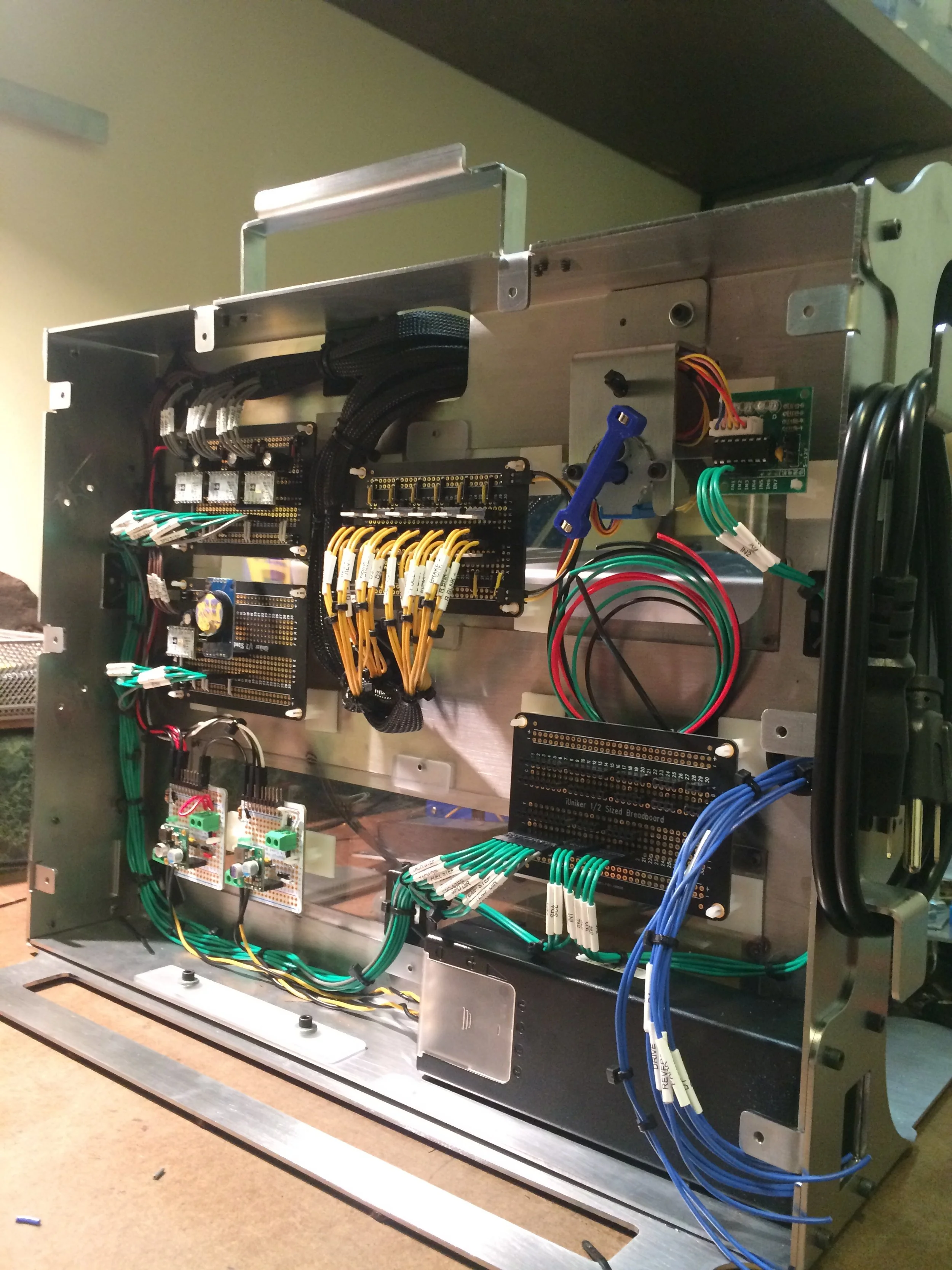
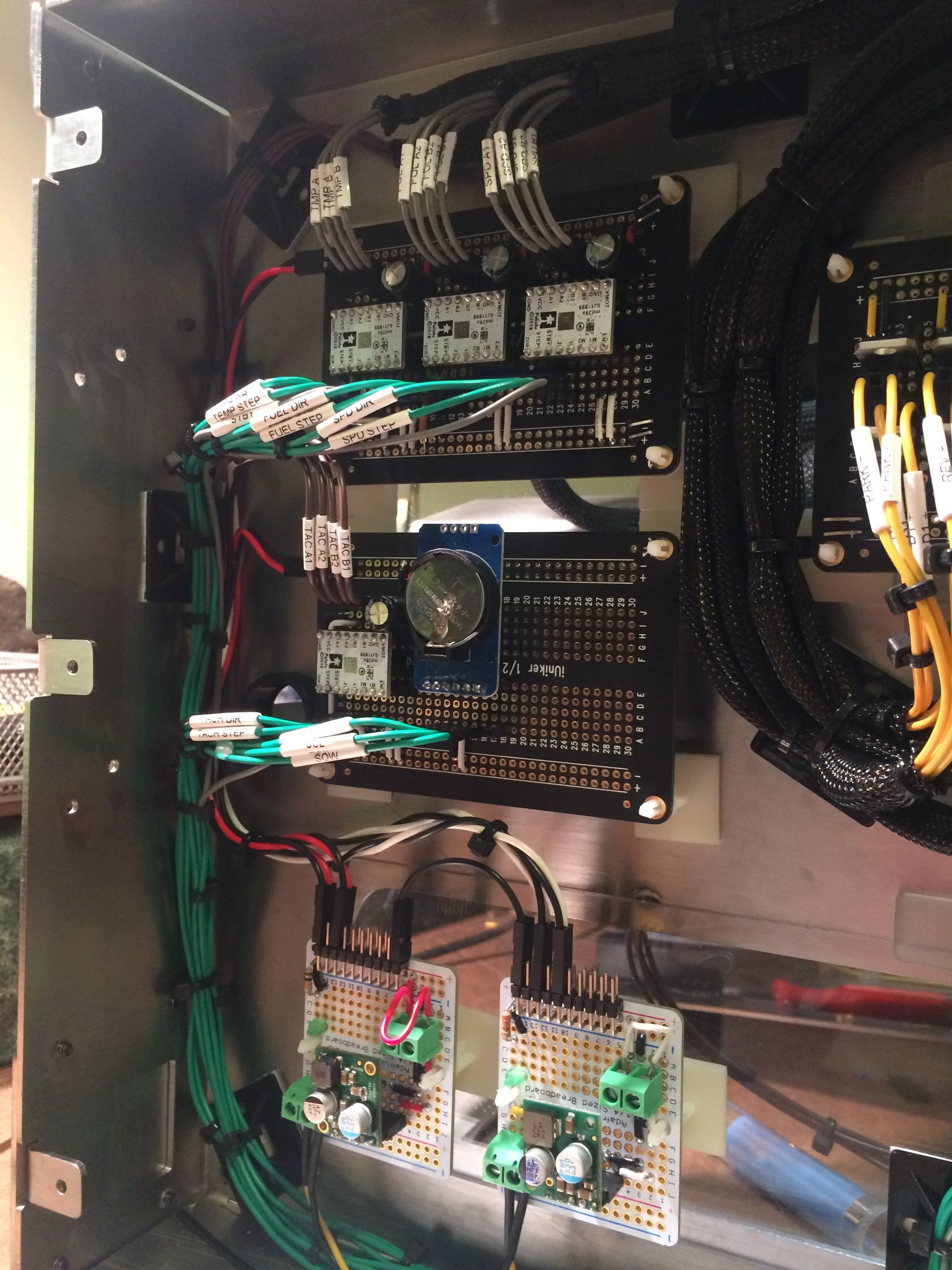
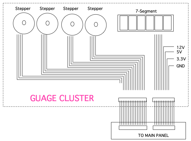
Hardware Design
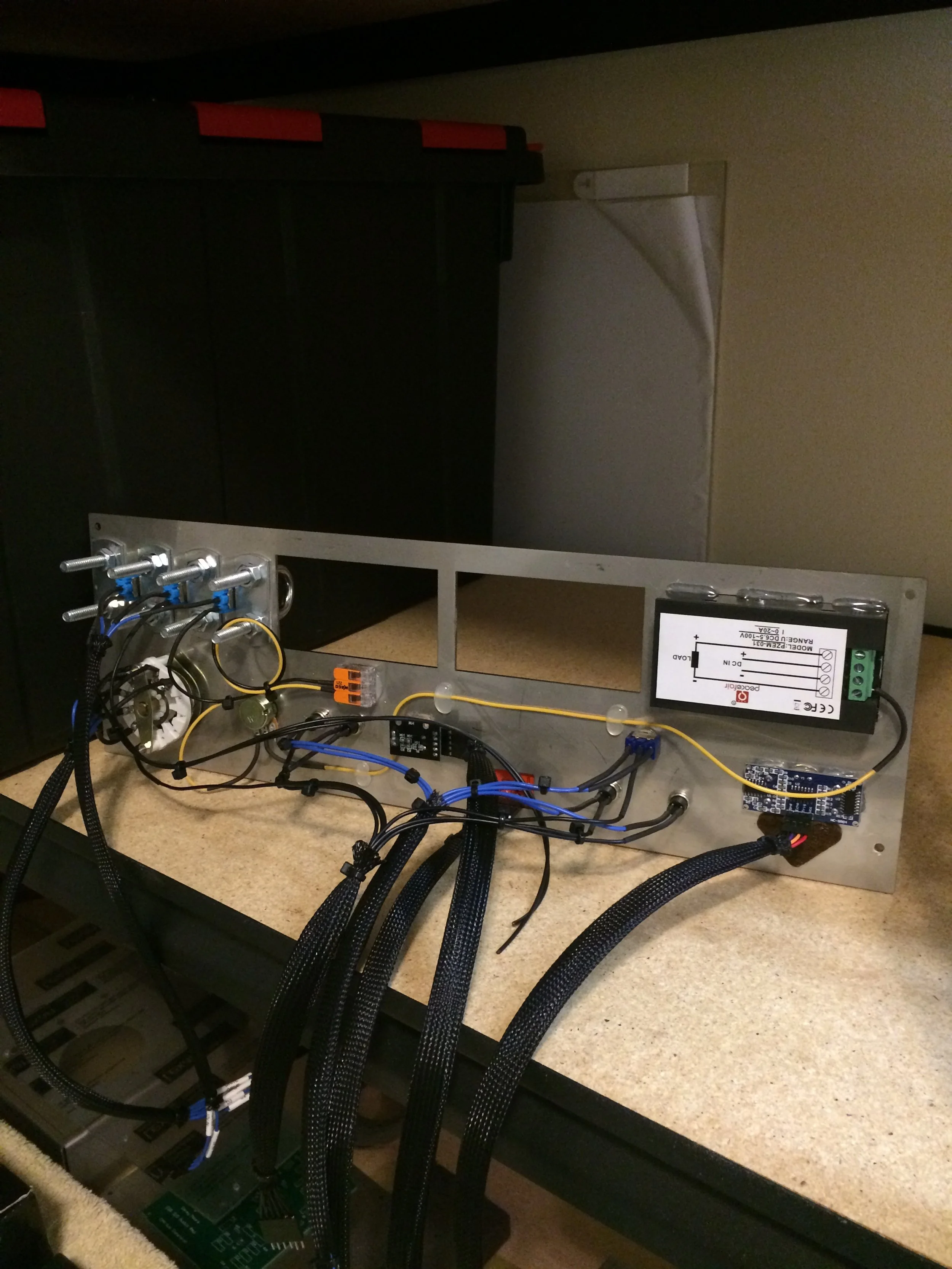
The system integrates the microcontroller, control panel, gauge cluster, and display components through a structured wiring architecture. A detailed I/O mapping strategy was developed to manage over 40 connections, including GPIO, timers, and communication interfaces. Custom wiring harnesses, labeling, and color coding improved reliability and reduced troubleshooting time. Multi-voltage power distribution (12V, 5V, 3.3V) was implemented to support all subsystems.


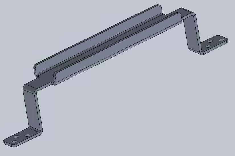
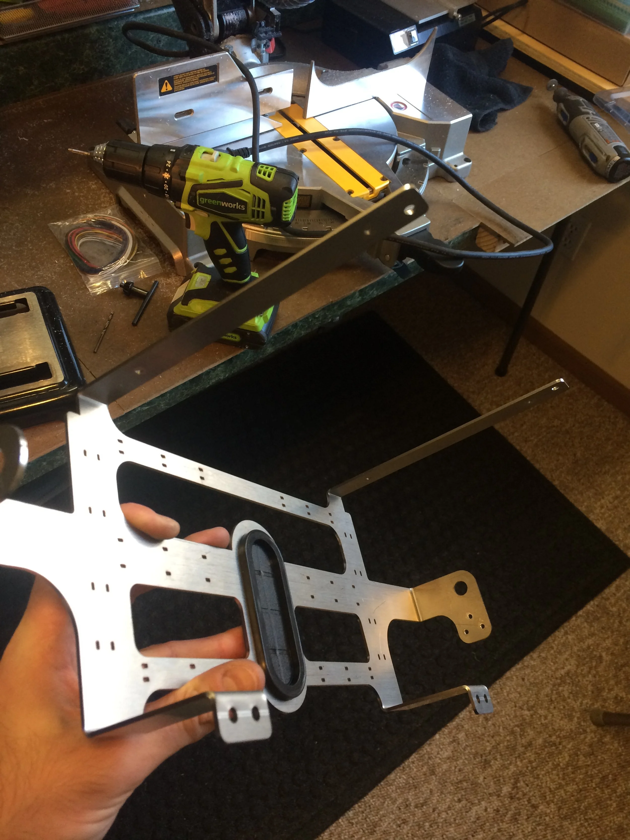
Mechanical Design
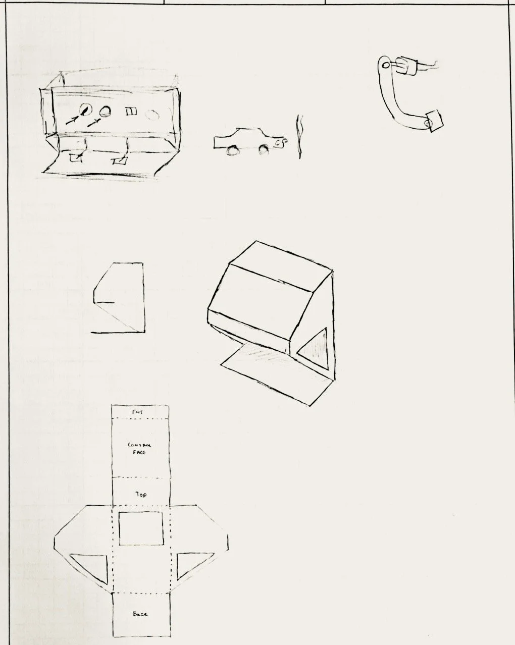
The enclosure was designed in SOLIDWORKS using sheet metal features and organized into four subassemblies: frame, electrical box, control panel, and cluster bracket. The design supports full system integration while maintaining accessibility for wiring, assembly, and maintenance.
Functional features include a carry handle, cord management brackets, and an adjustable mounting system that allows the gauge cluster to rotate for improved visibility during operation.


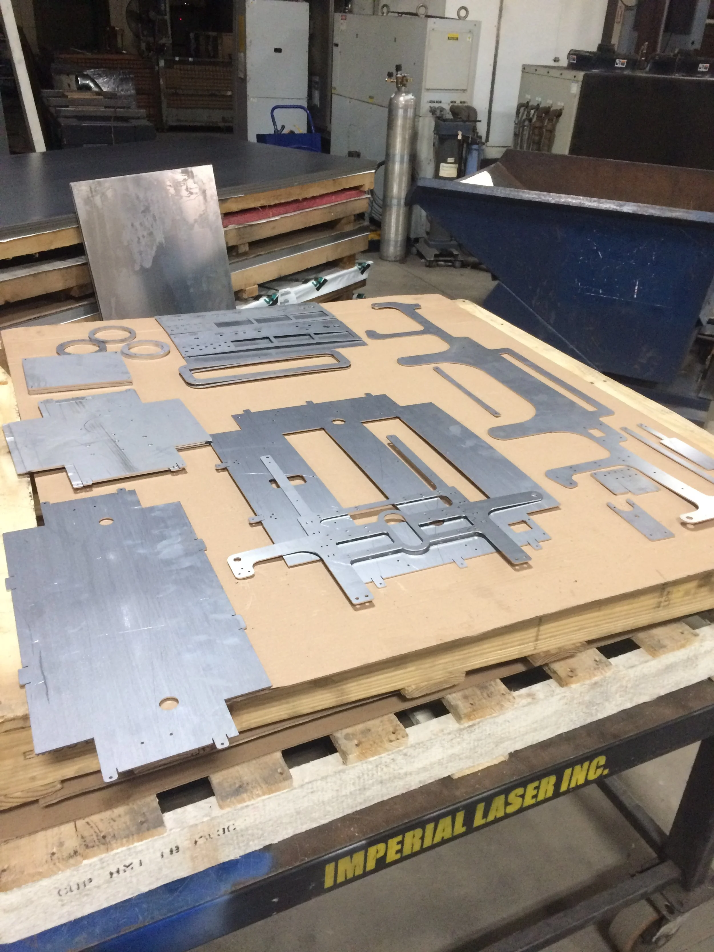
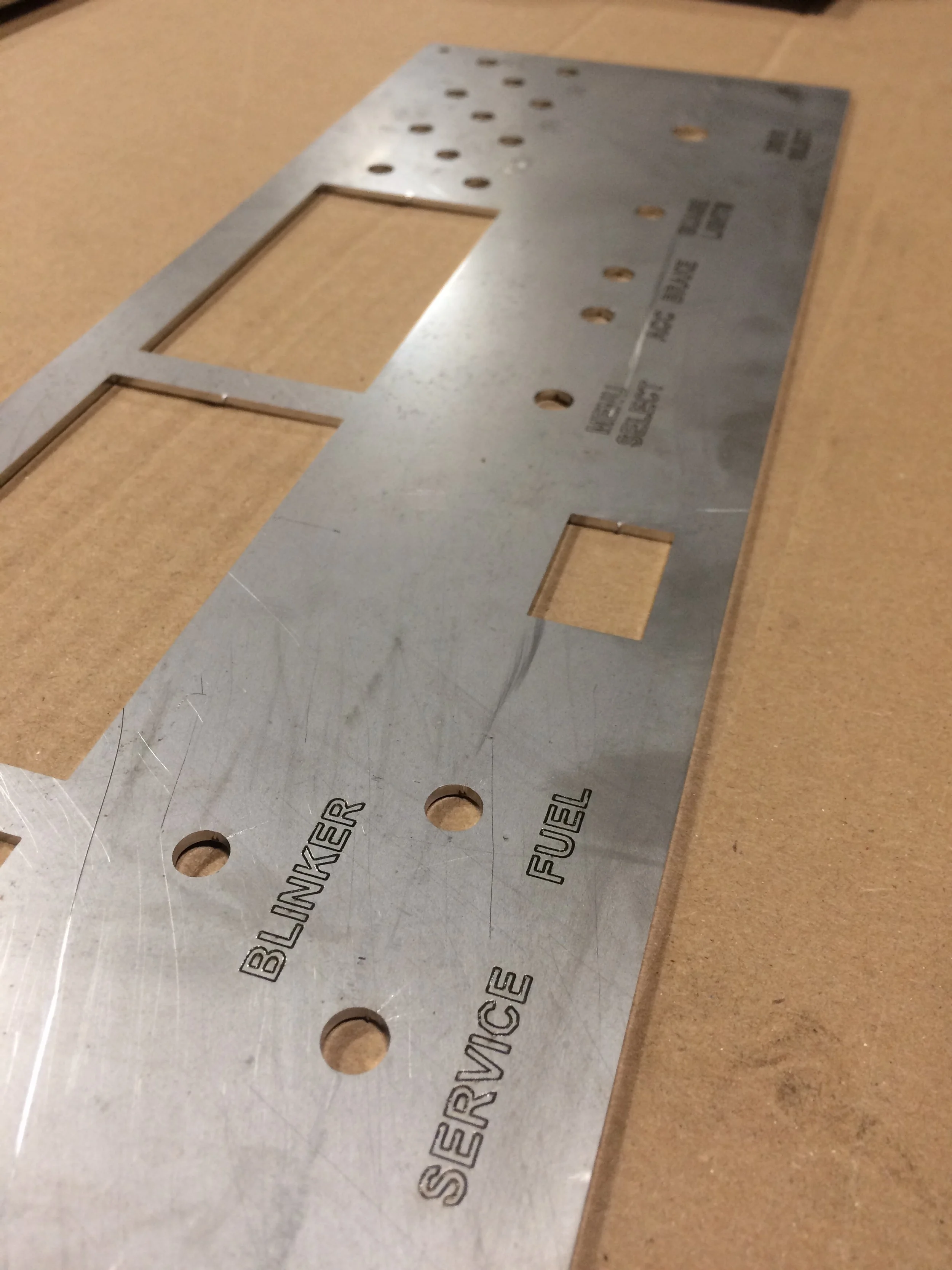
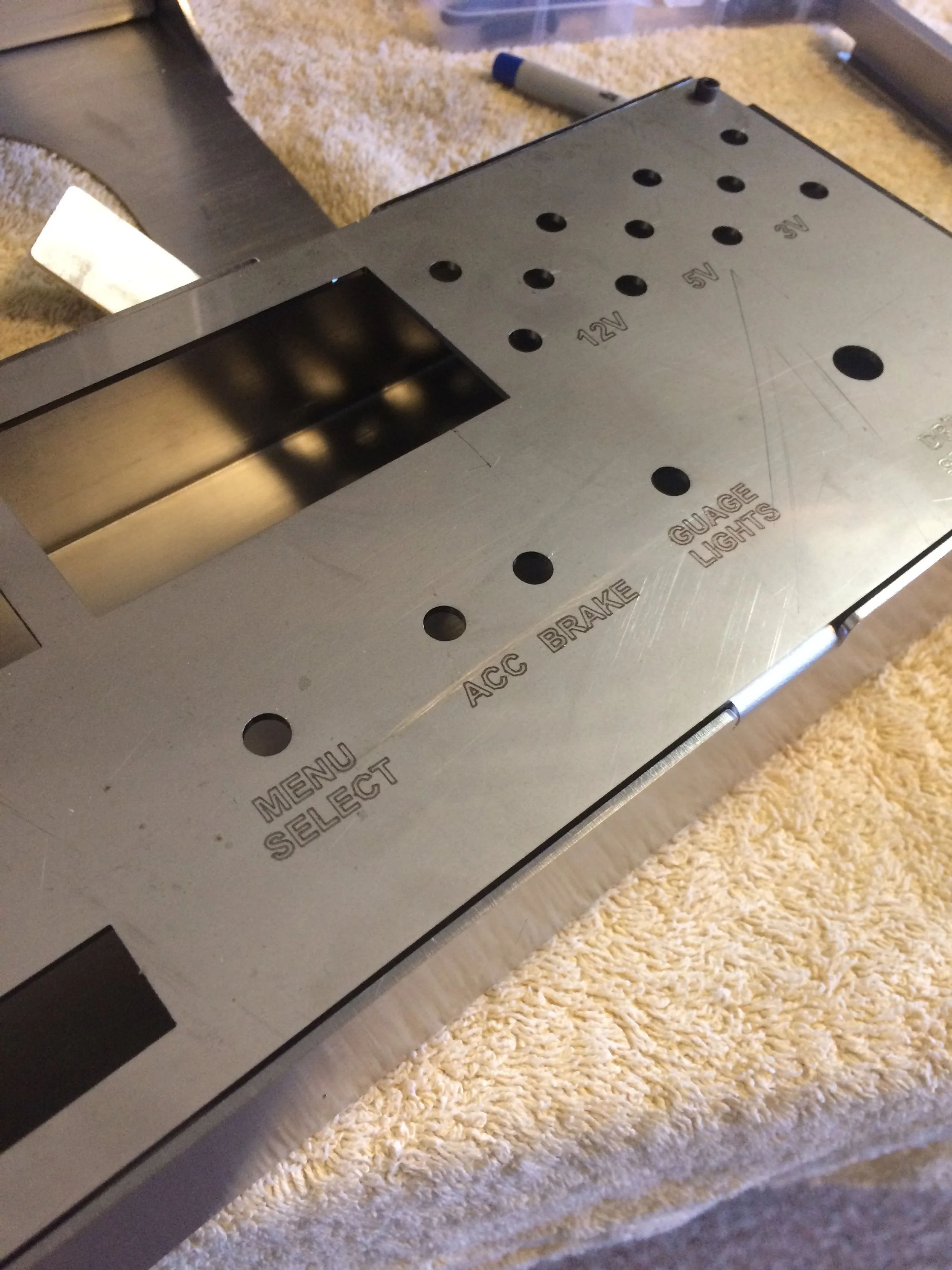
Fabrication
The enclosure was fabricated from 316 stainless steel using laser cutting and press brake forming. Components were designed for manufacturability, with features such as bend allowances, mounting points, and threaded fastener integration.
Each subassembly was assembled using mechanical fasteners, allowing for modular construction and easy access during integration and maintenance. A clear polycarbonate rear panel was incorporated to provide visibility into internal components during operation and debugging.
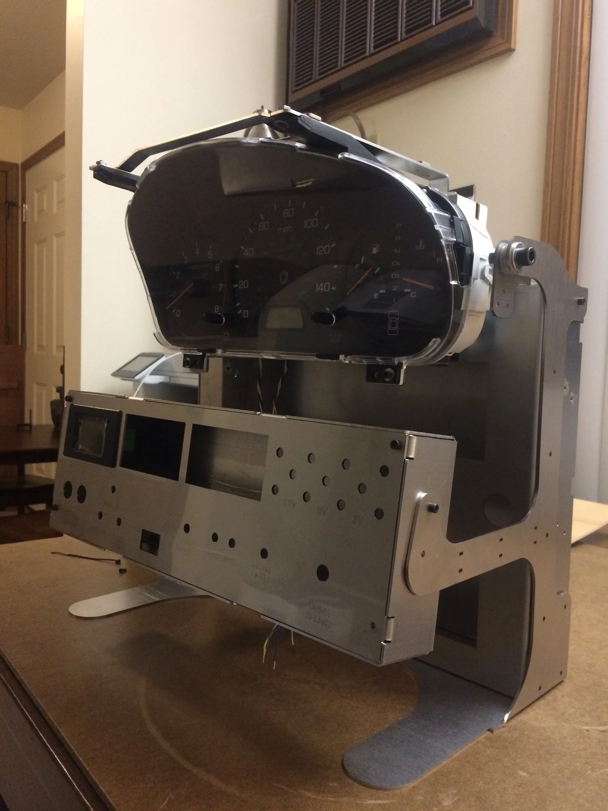
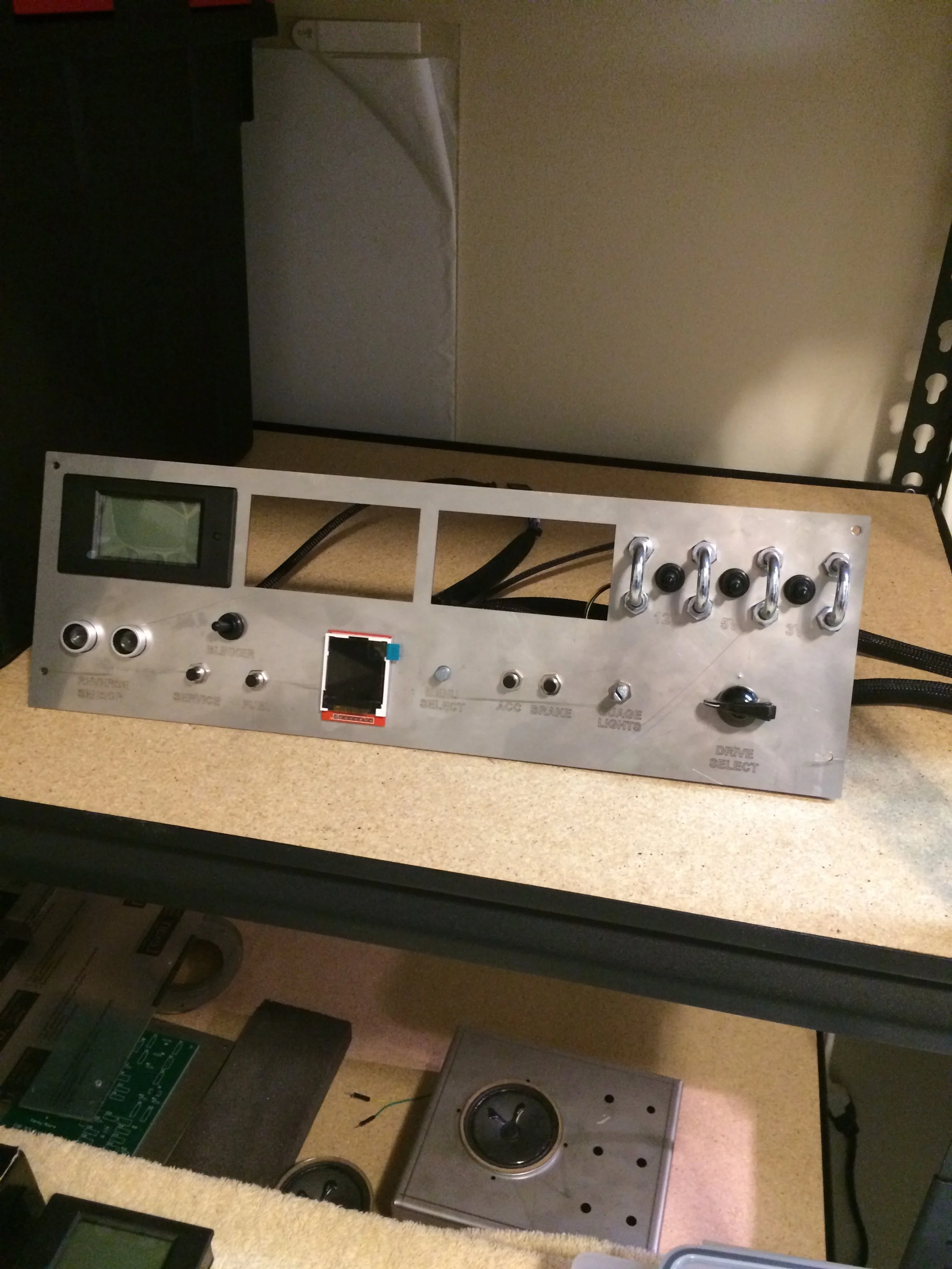
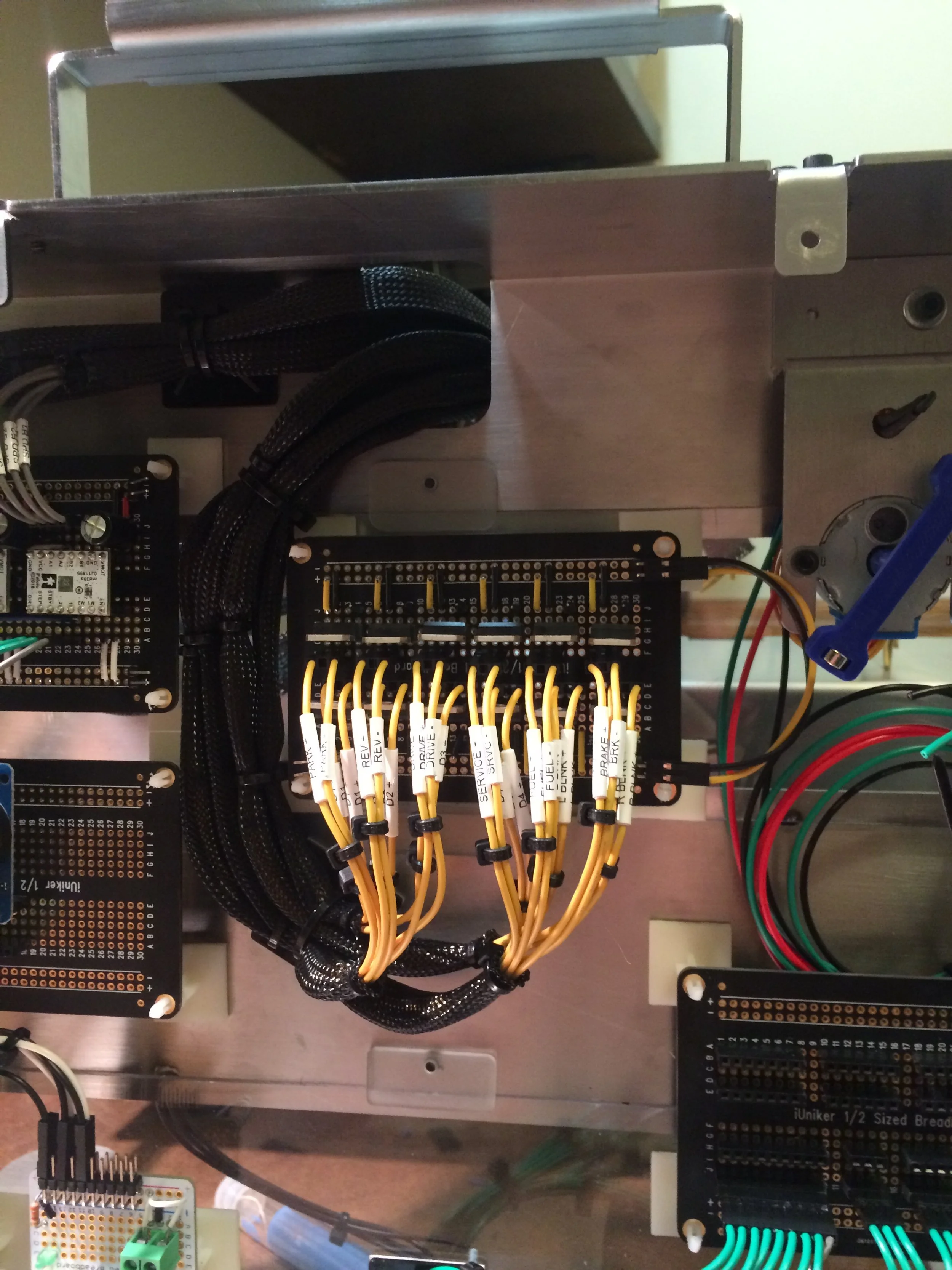
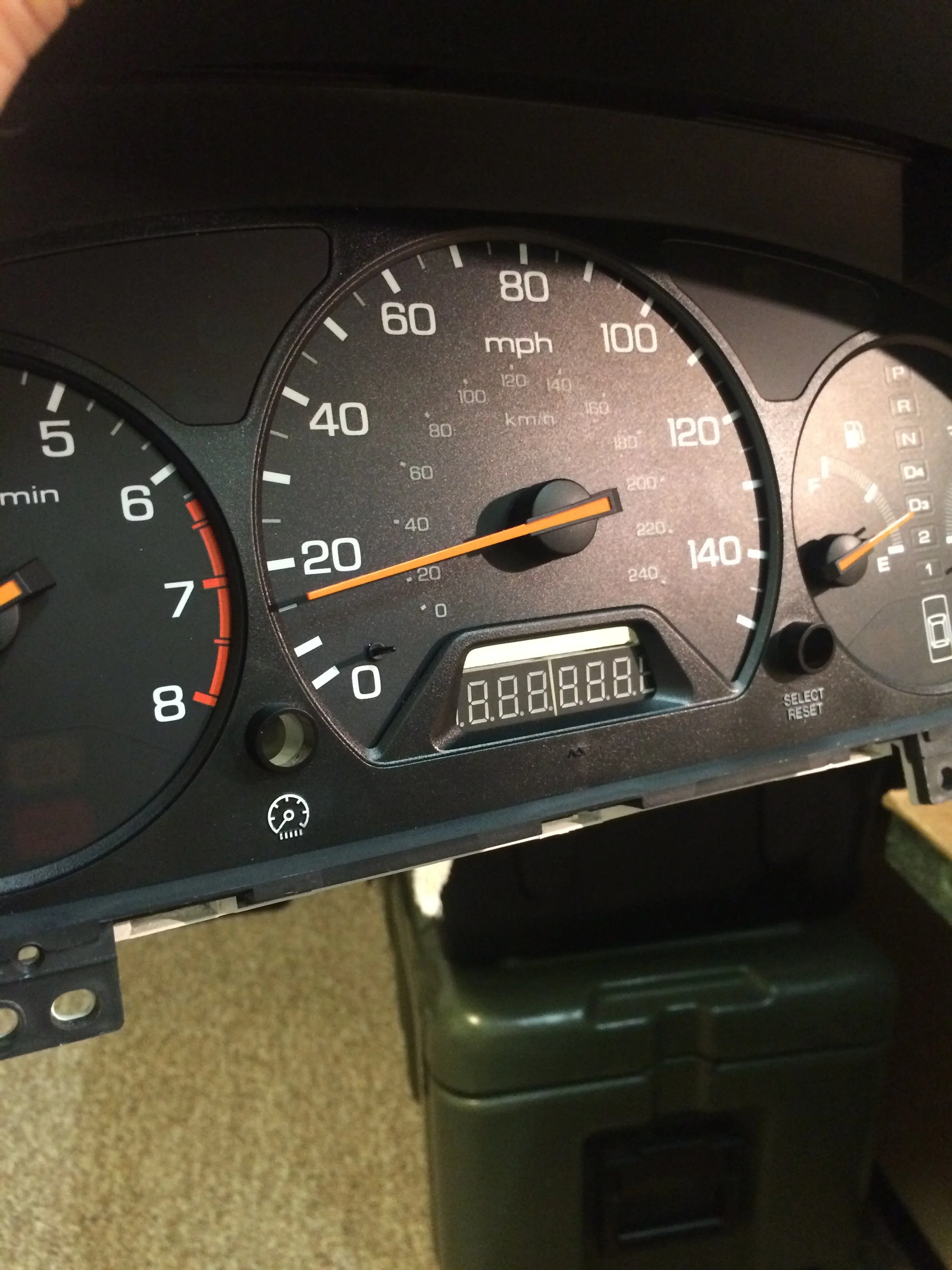
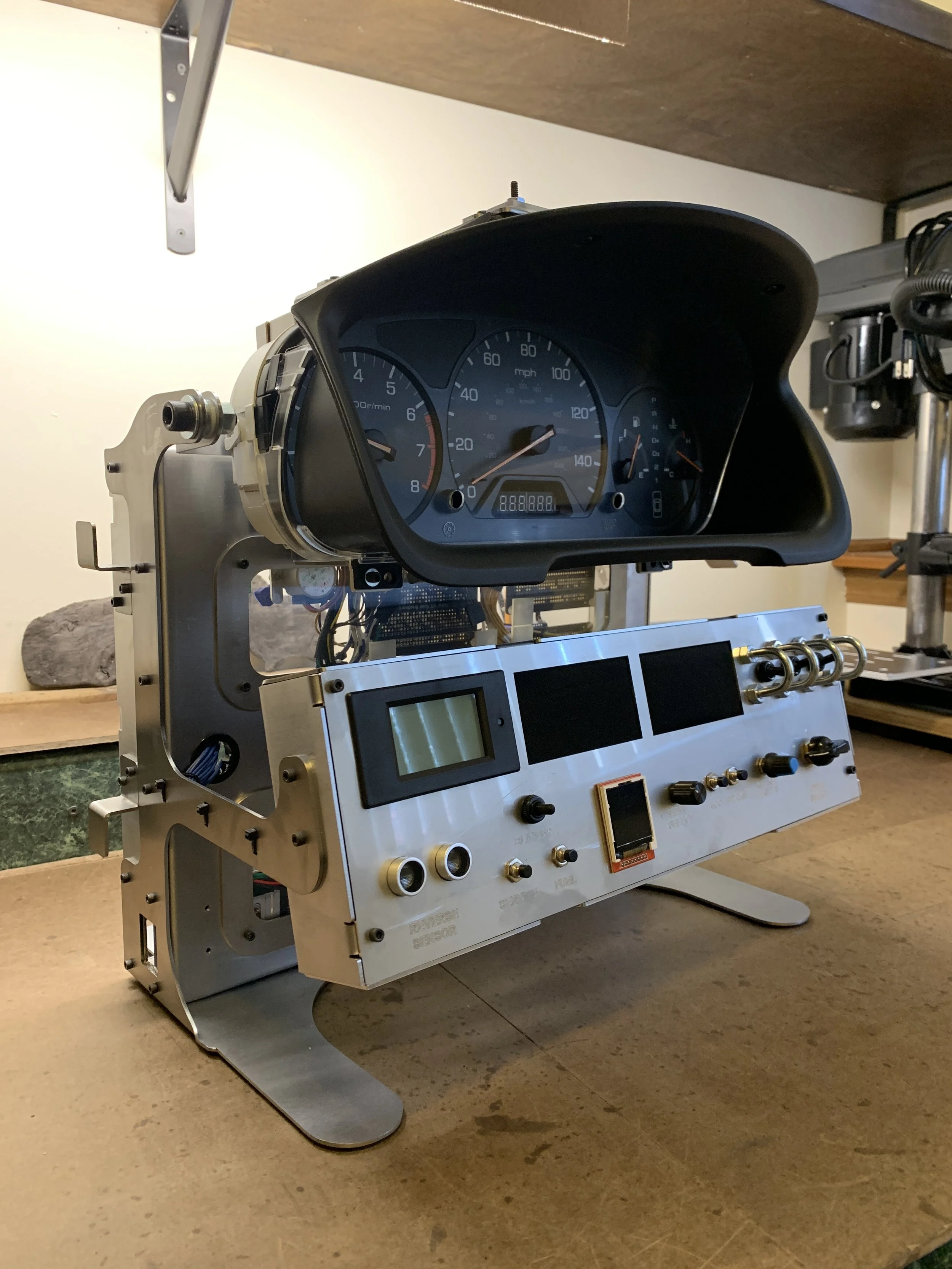
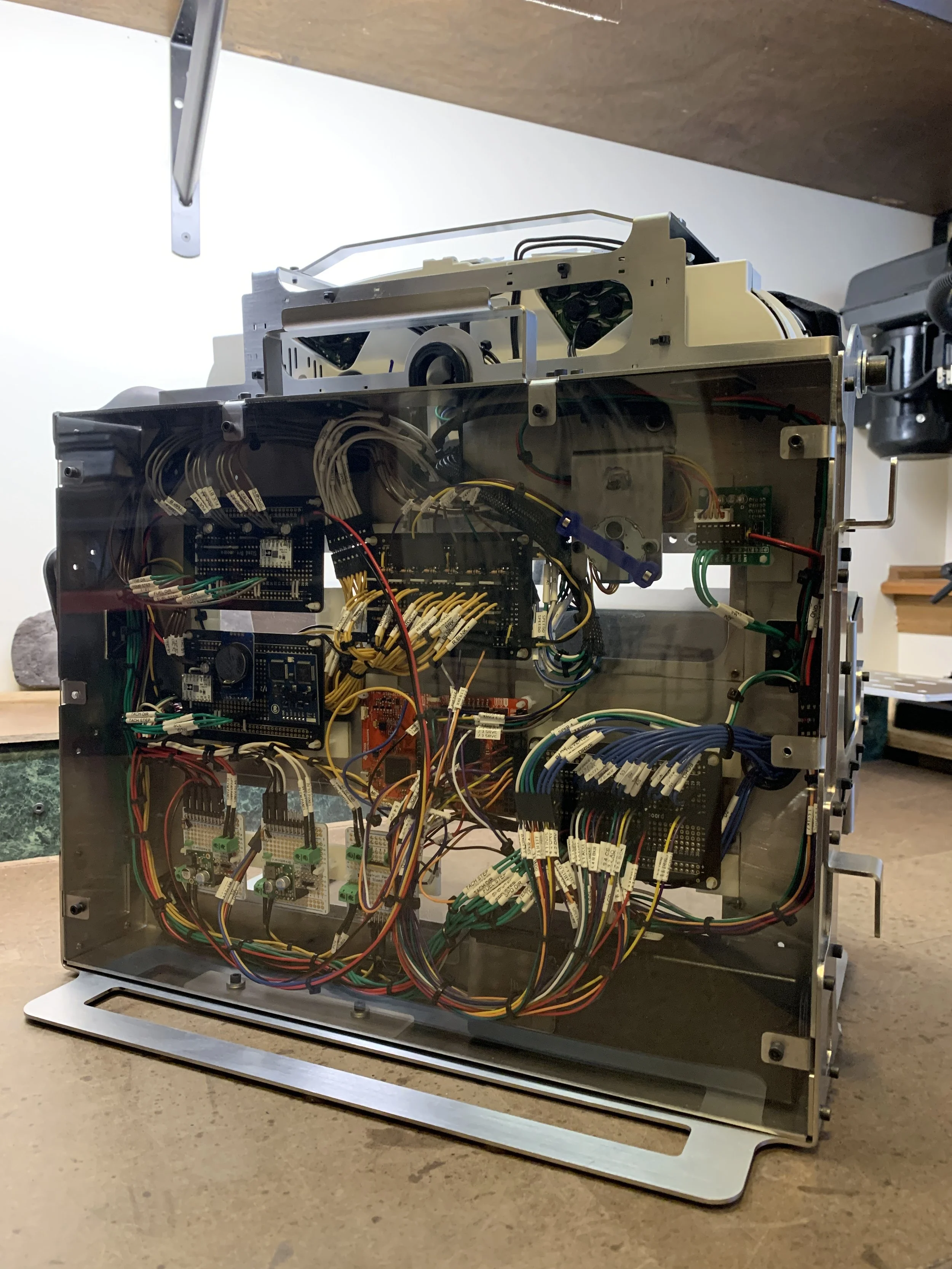
Results
The completed system integrates mechanical, electrical, and software components into a functional automotive-style gauge cluster. The front view demonstrates the user interface and control panel, while the rear view highlights the internal wiring architecture, power distribution, and system-level integration.
Videos
Watch on Youtube
Gauge Startup
Button Speed Control
RTC / Fault Screen Testing