Development Board Test Fixture
Jan 2022 - Aug 2022

Overview
A Capstone project requiring the design and production of 10 devices capable of testing the hardware components of Arduino and STM32 microcontrollers. Funded by GVSU’s Engineering Department, this tool allows 1st and 2nd year engineering students to quickly check the health of their development boards.
-
Team Captain:
Hosted weekly meetings
Set project goals and timelines
Distributed work loads across team members
Tracked and reported progress
Managed budget
Ensured the team had every resource needed to be successful
Mechanical Design and Fabrication:
Responsible for overall mechanical system design
Performed material selection
Manufactured components using CNC machining and 3D printing
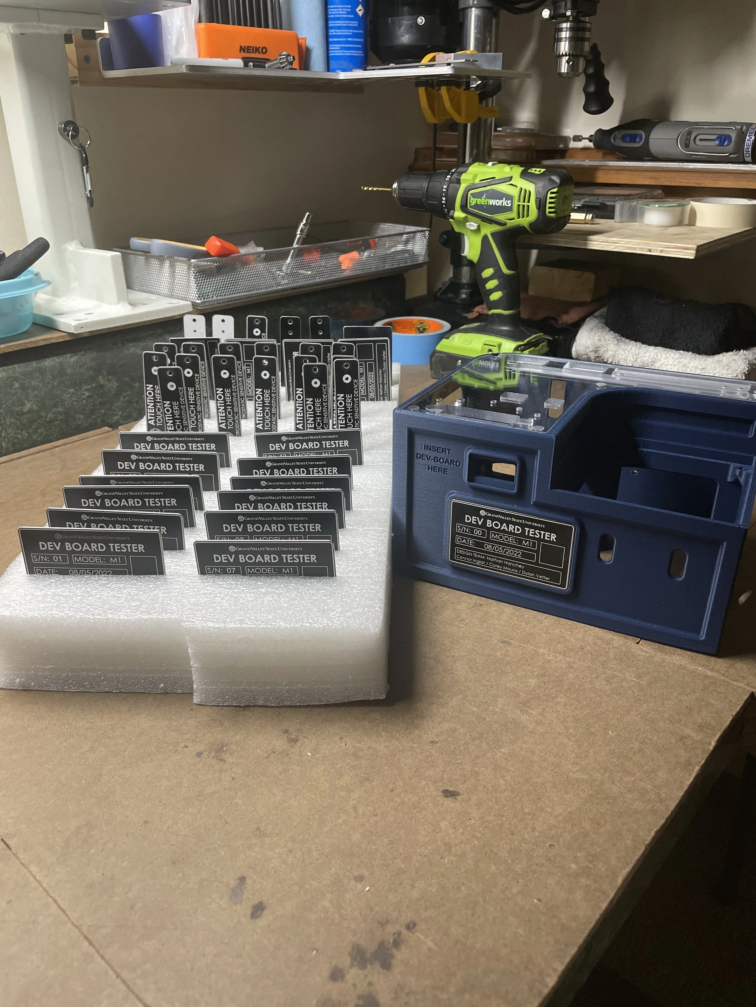
Laser cut and etched ESD grounding plate and front placard
Managed part tracking and production of final units
Electrical and System Integration
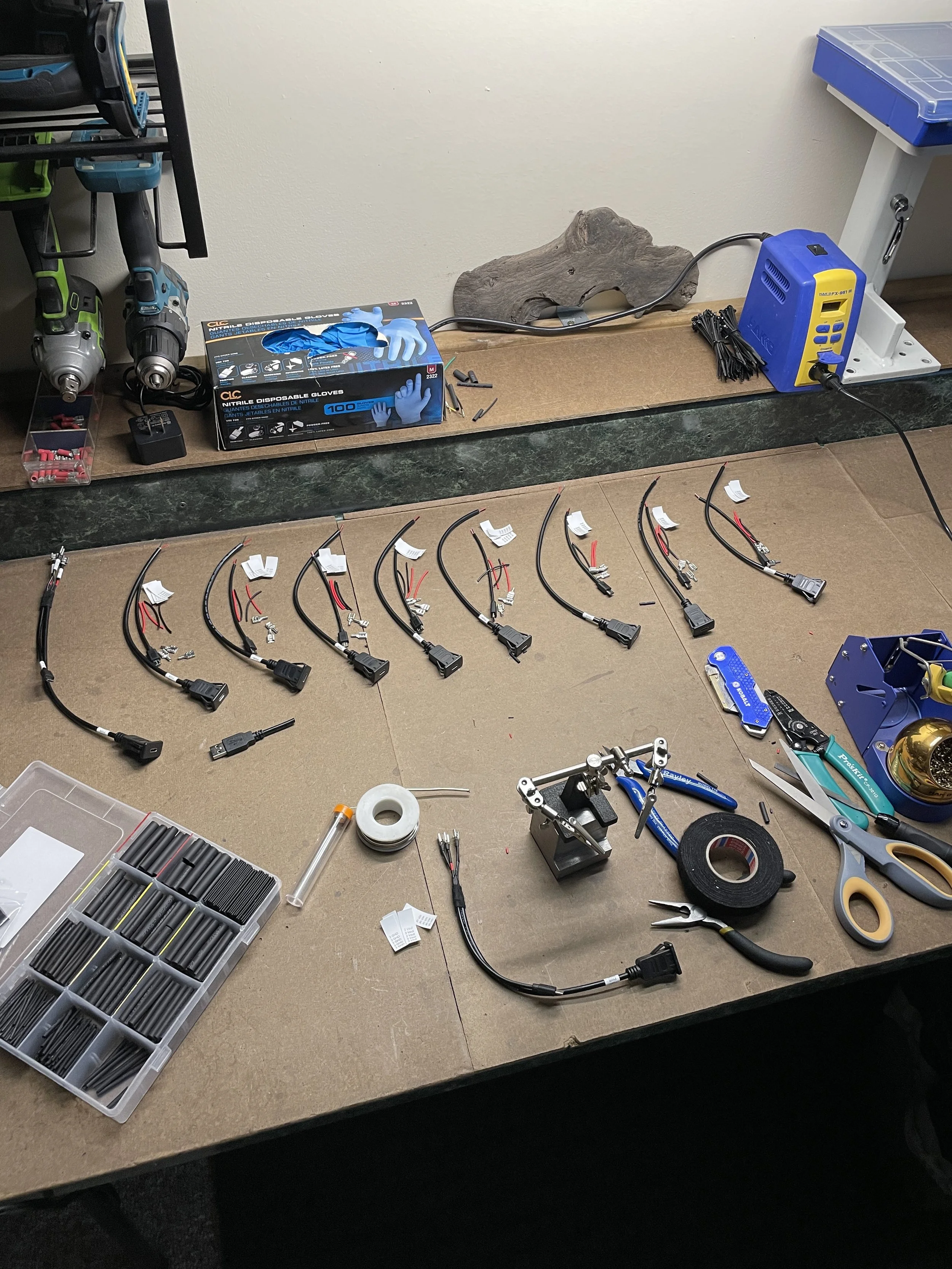
Built wiring harnesses and integrated electrical components
Contributed to software architecture design, including coordination between Raspberry Pi control software and subject board test routines
Participated in system validation and hardware testing to verify functionality across deployed units
-
Many engineering courses requier students to build and program microcontroller-based hardware systems. Incorrect wiring or faulty components can damage GPIO pins, voltage regulators, or entire boards, often making it difficult to determine whether failures are hardware or software-related.
Diagnosing these issues is time-consuming and resource-intensive, especially in environments where multiple students require support.
This project addresses that challenge by providing a dedicated hardware testing system capable of validating Arduino Uno and STM32 boards through automated test routines, allowing users to quickly identify hardware faults and isolate software related issues.
-
Challenges:
Limited team composition (no dedicated mechanical engineer)
Budget constraints and supply chain delays during COVID
Component sourcing required early procurement across multiple vendors
Tradeoff between shipping costs vs timeline reliability
Outcomes:
Delivered 20 fully assembled PCBs and ~300 3D-printed components
Maintained schedule across a 9-month development cycle
Shifted to in-house production to reduce vendor dependency
Delivered a functional testing system for student hardware validation
Explore This Project
Ideation
During the pandemic and the period immediately following, cost and resource availability were significant constraints due to ongoing supply chain disruptions. This required close collaboration with the client to define realistic expectations while still meeting core design objectives, including ease of use, portability, cost, robustness, and scalability.


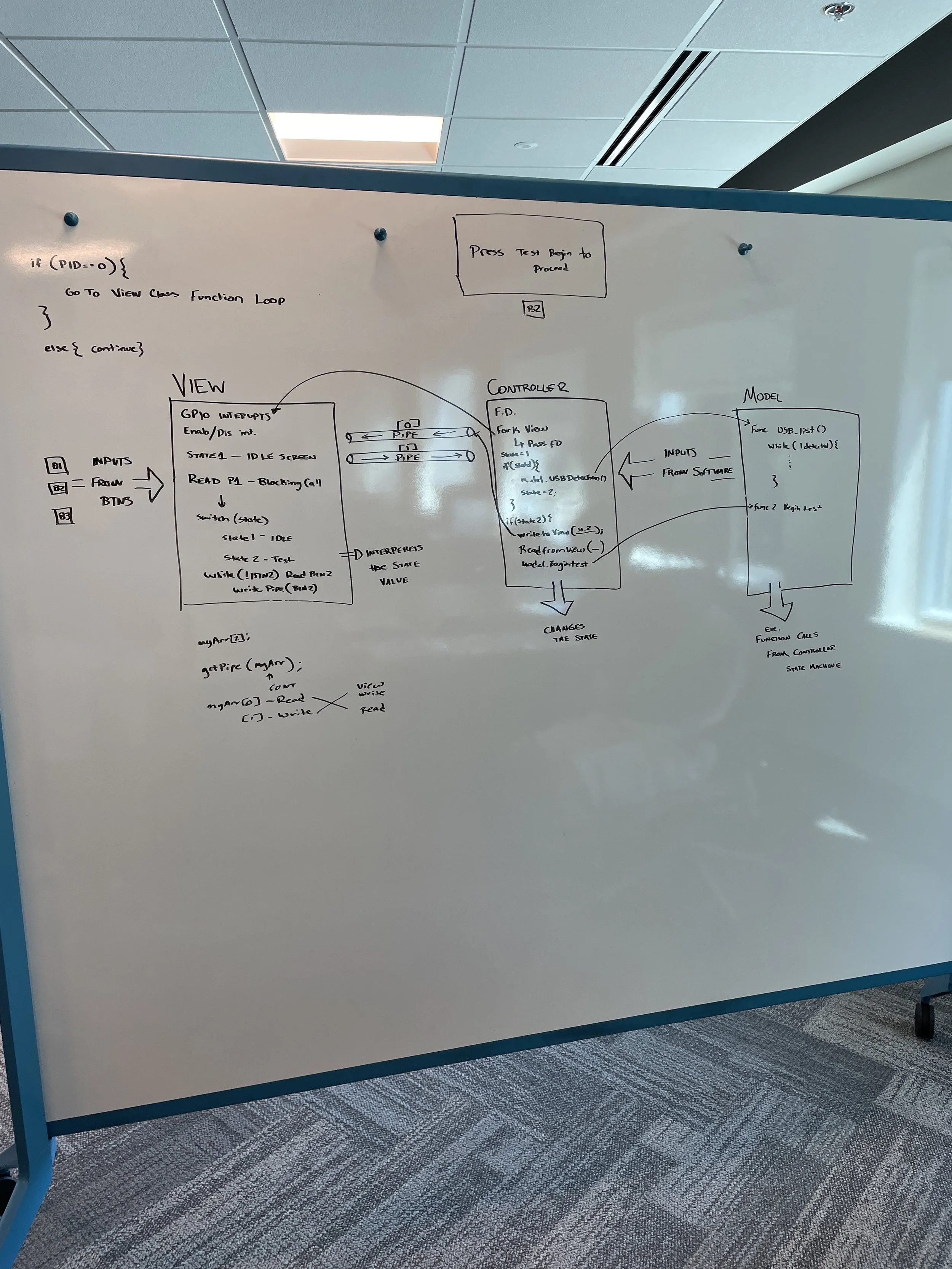
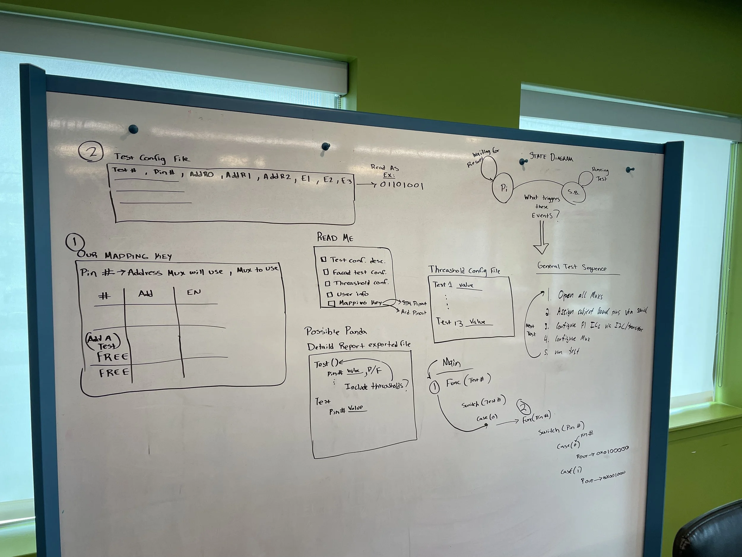

Software Design
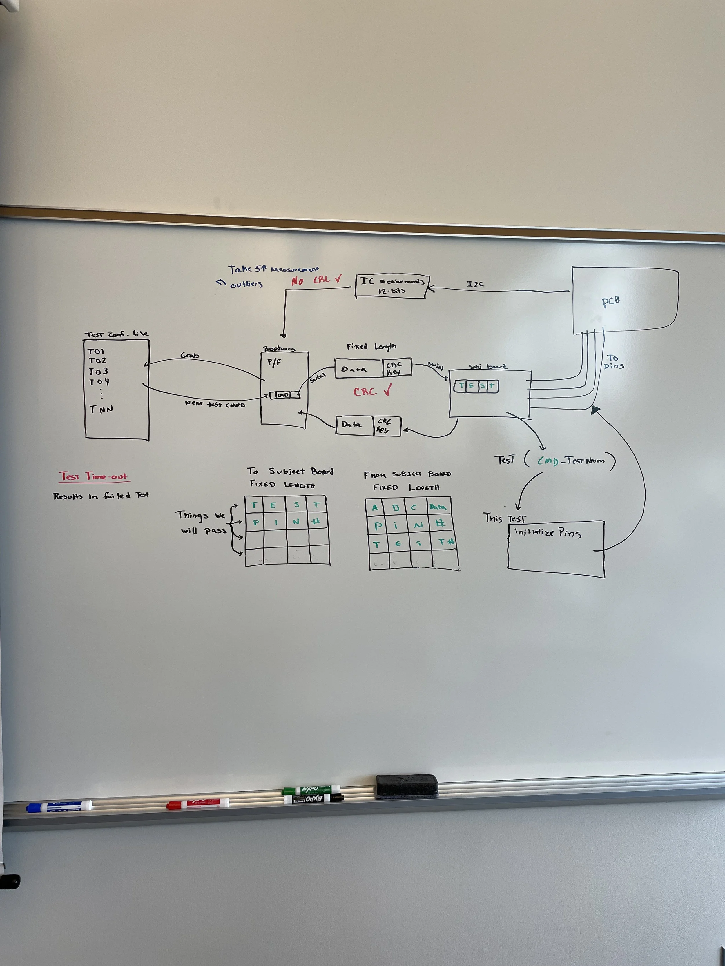
The system uses two programs to control the testing process. The first runs on a Raspberry Pi, which manages the GUI and sends test criteria to the subject board. The second program is flashed onto the subject board at the start of testing and configures pin behavior for each test.
Serial communication is used throughout testing to coordinate data exchange between the controller and the subject board.


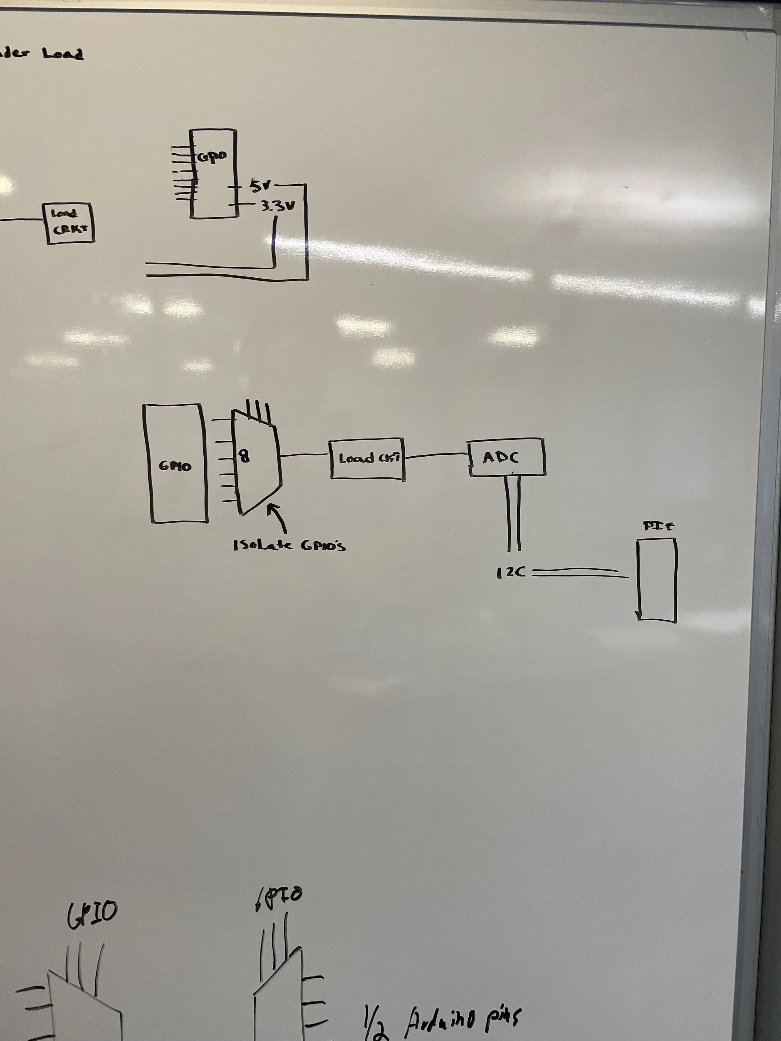
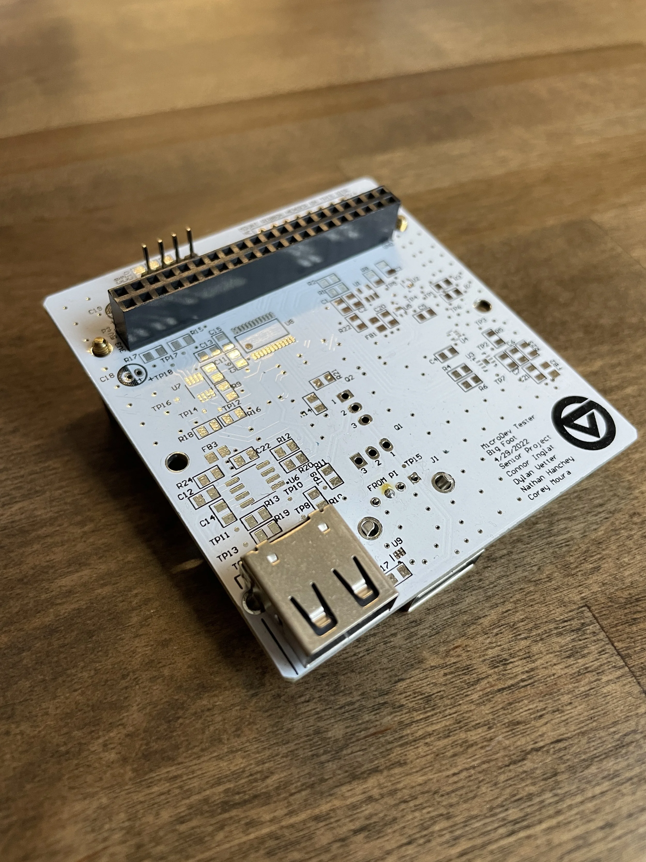
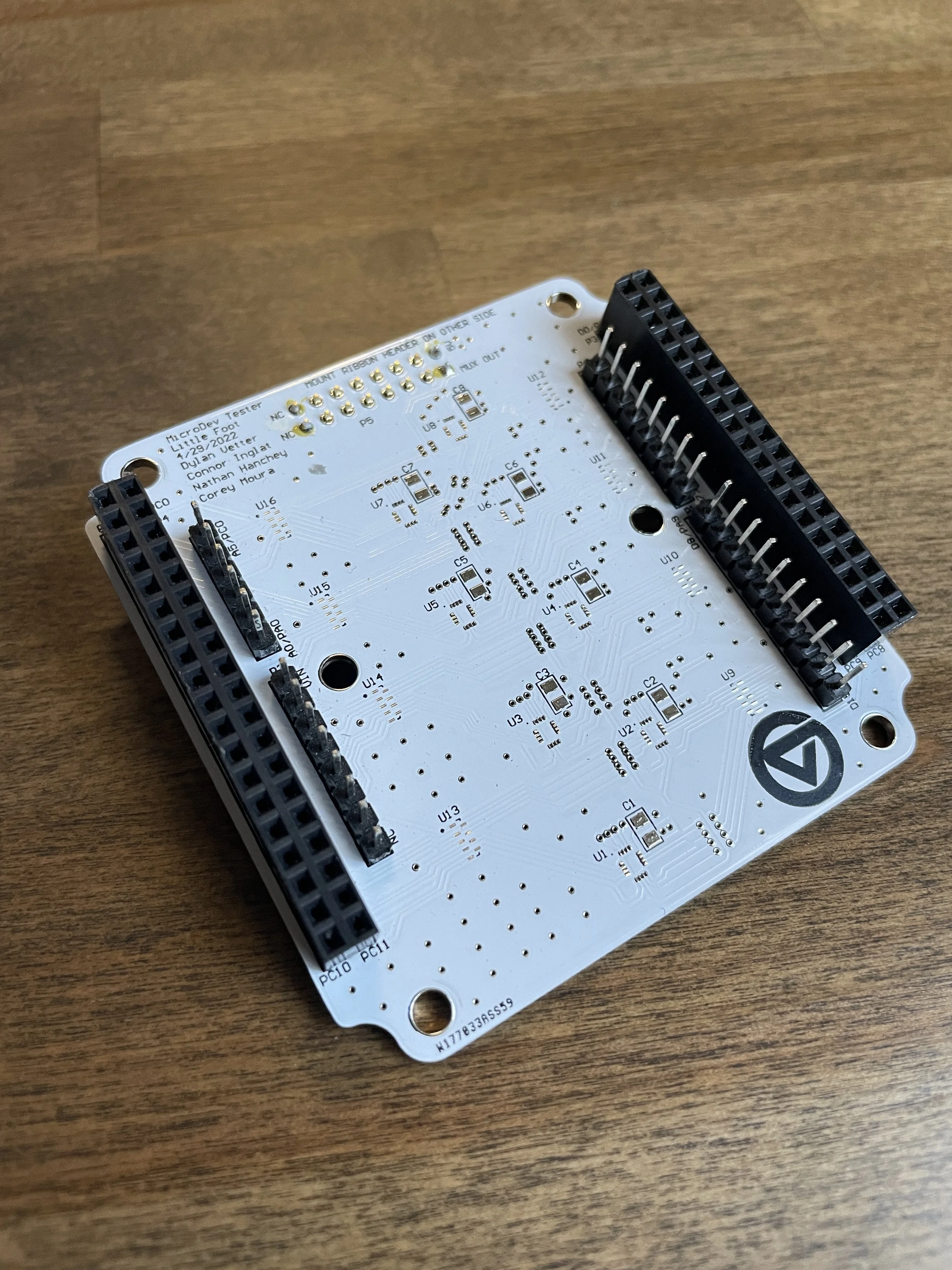
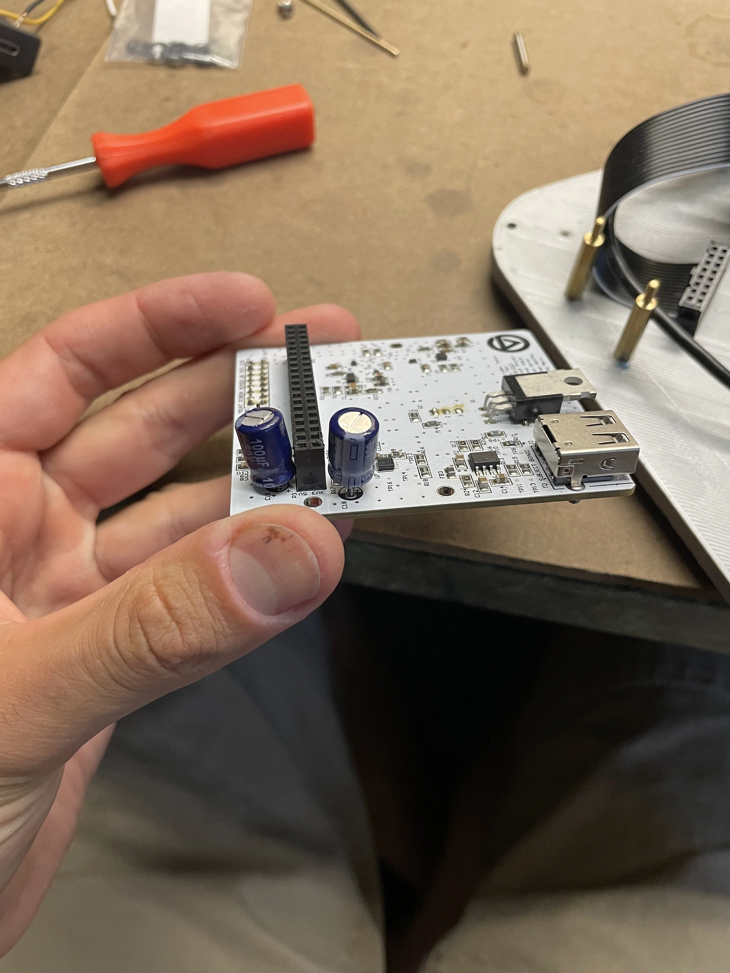
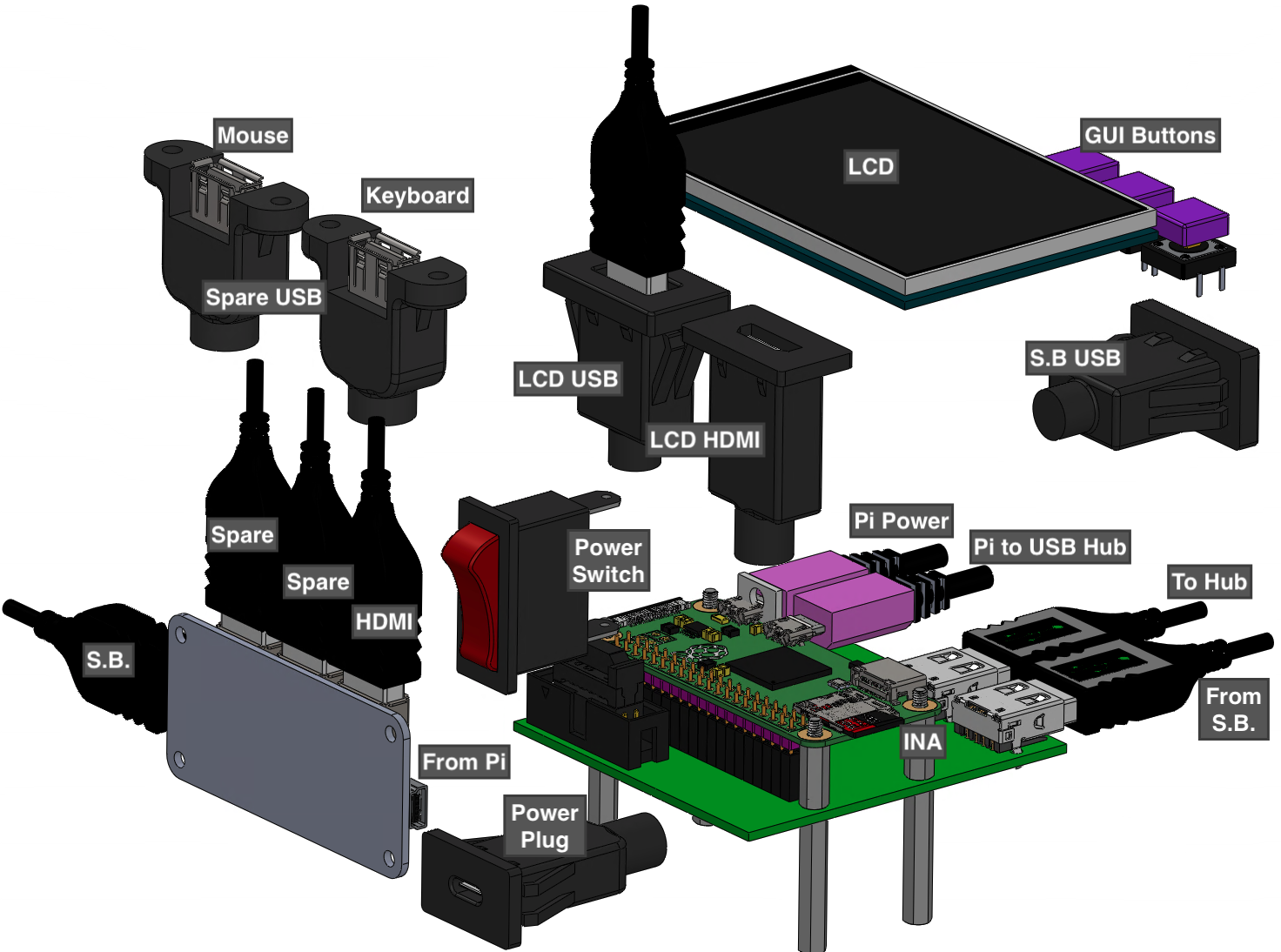
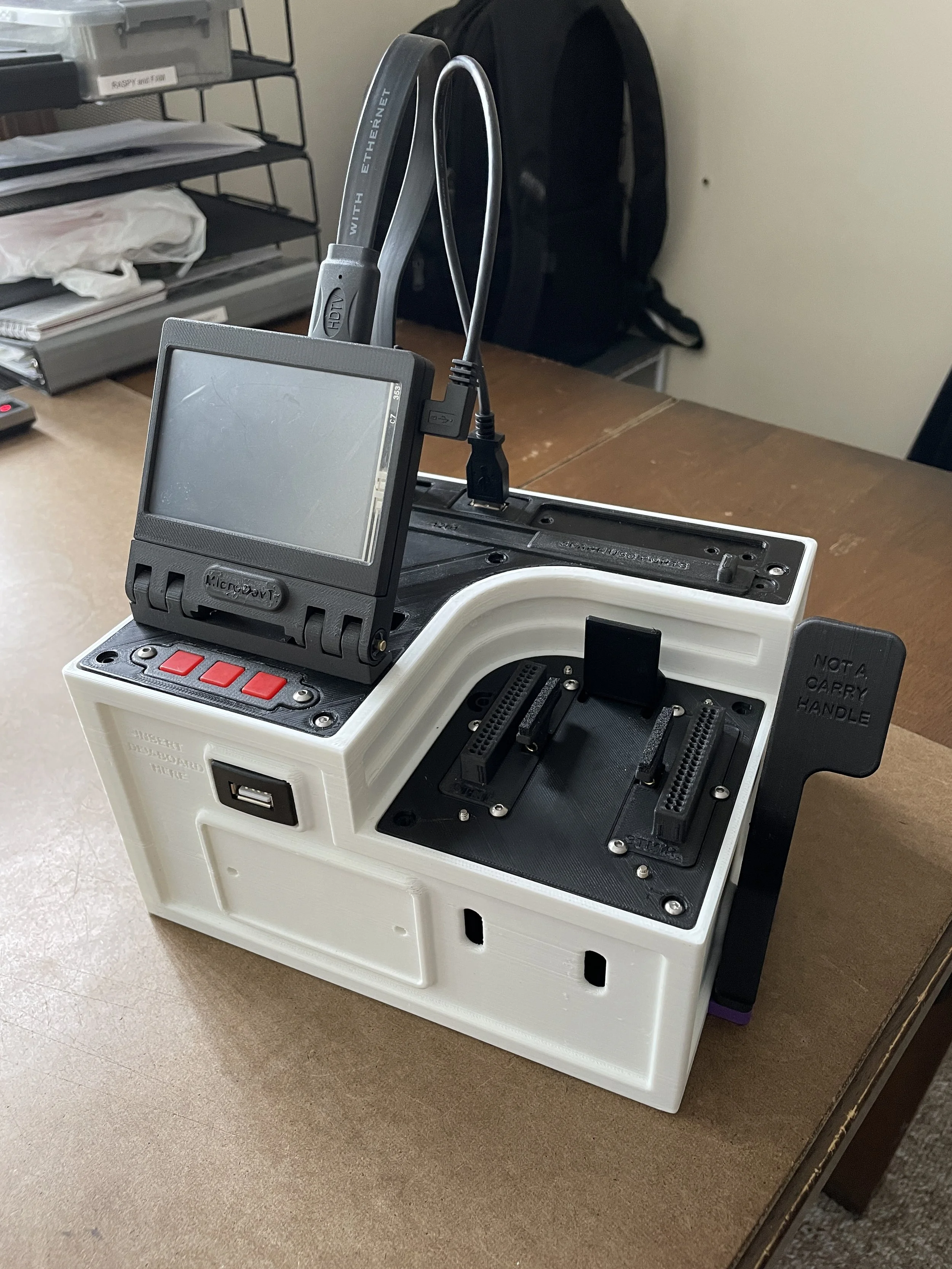
PCB Design
The system uses two custom PCBs that work together during testing. The Little Foot PCB provides the physical interface between the device and the subject board and includes multiplexers used to isolate pins during testing. The Big Foot PCB connects to the Raspberry Pi and contains the ADC, DAC, and INA ICs used for measuring pin outputs.
The PCB design was led by other team members; this section is included to illustrate how the hardware supports the overall testing system.


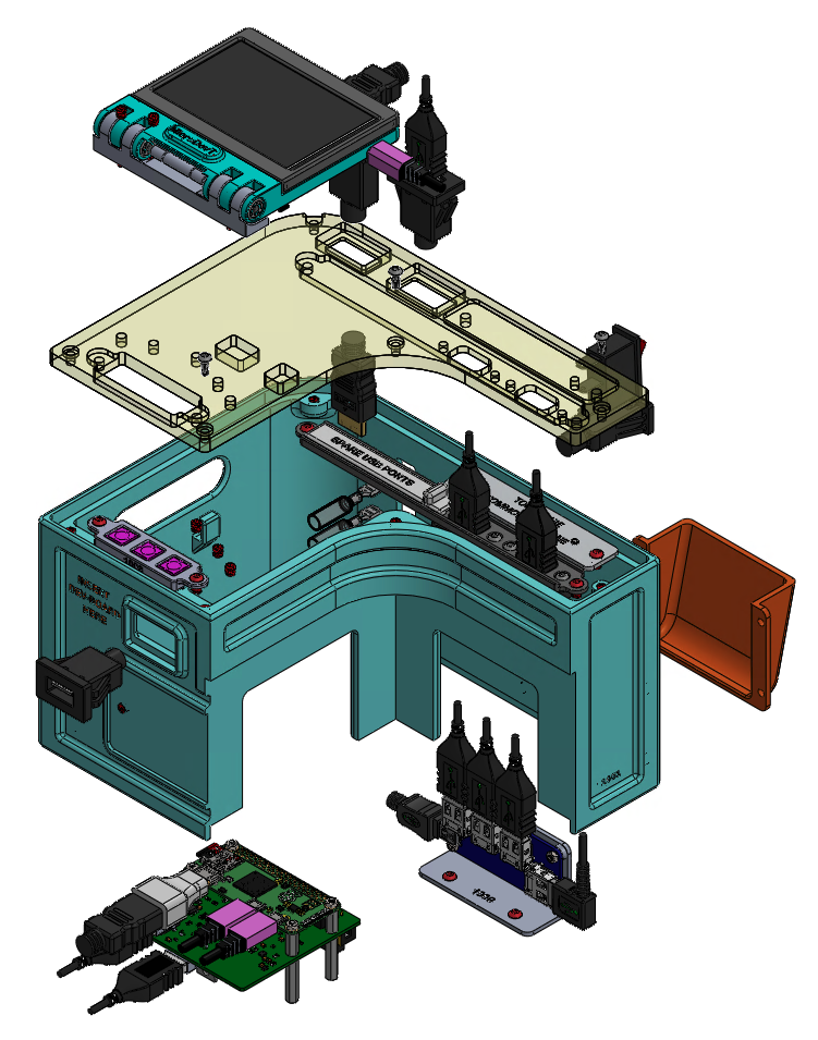
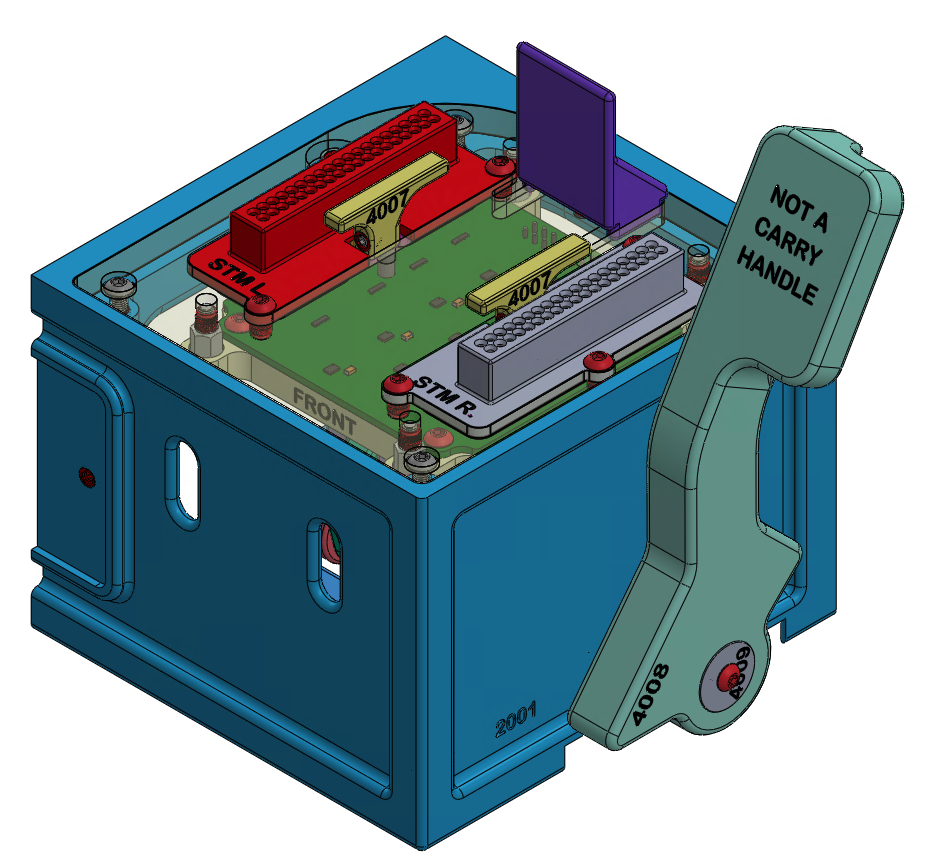
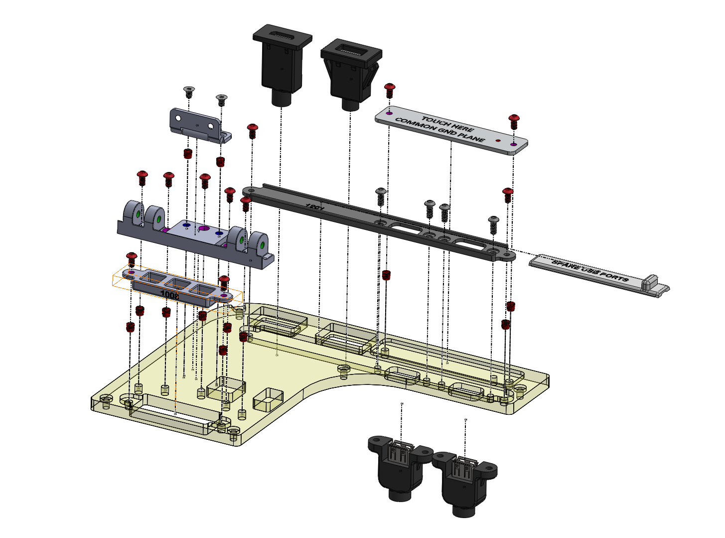
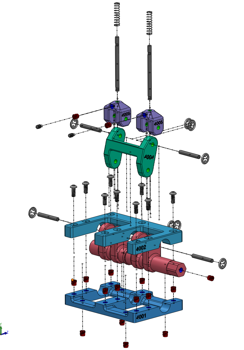
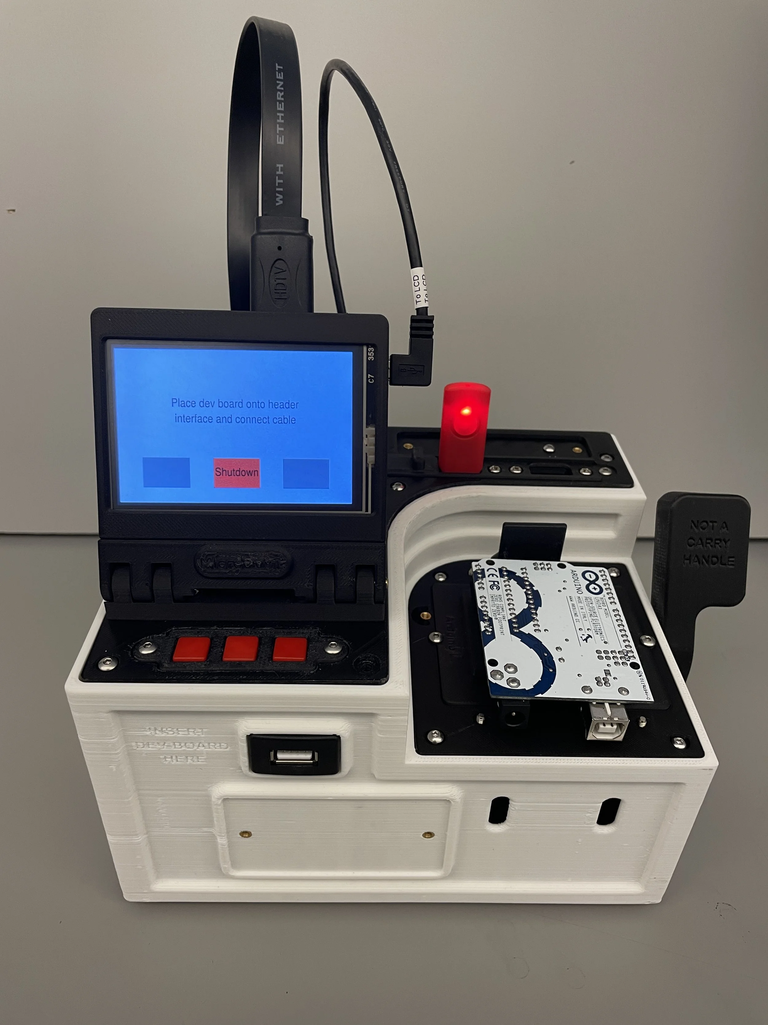
Mechanical Design
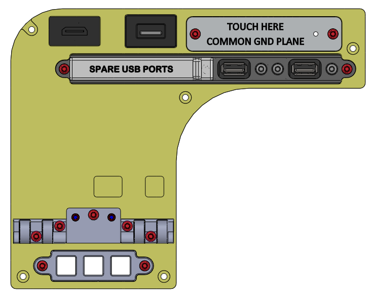
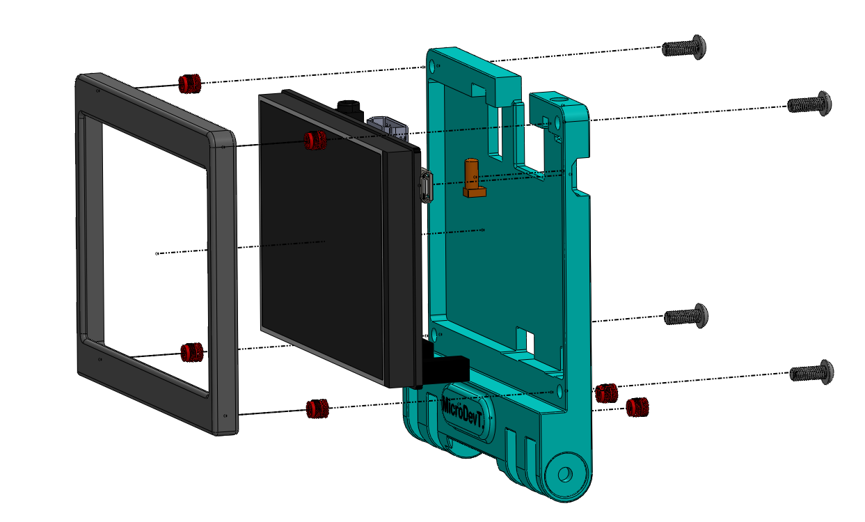
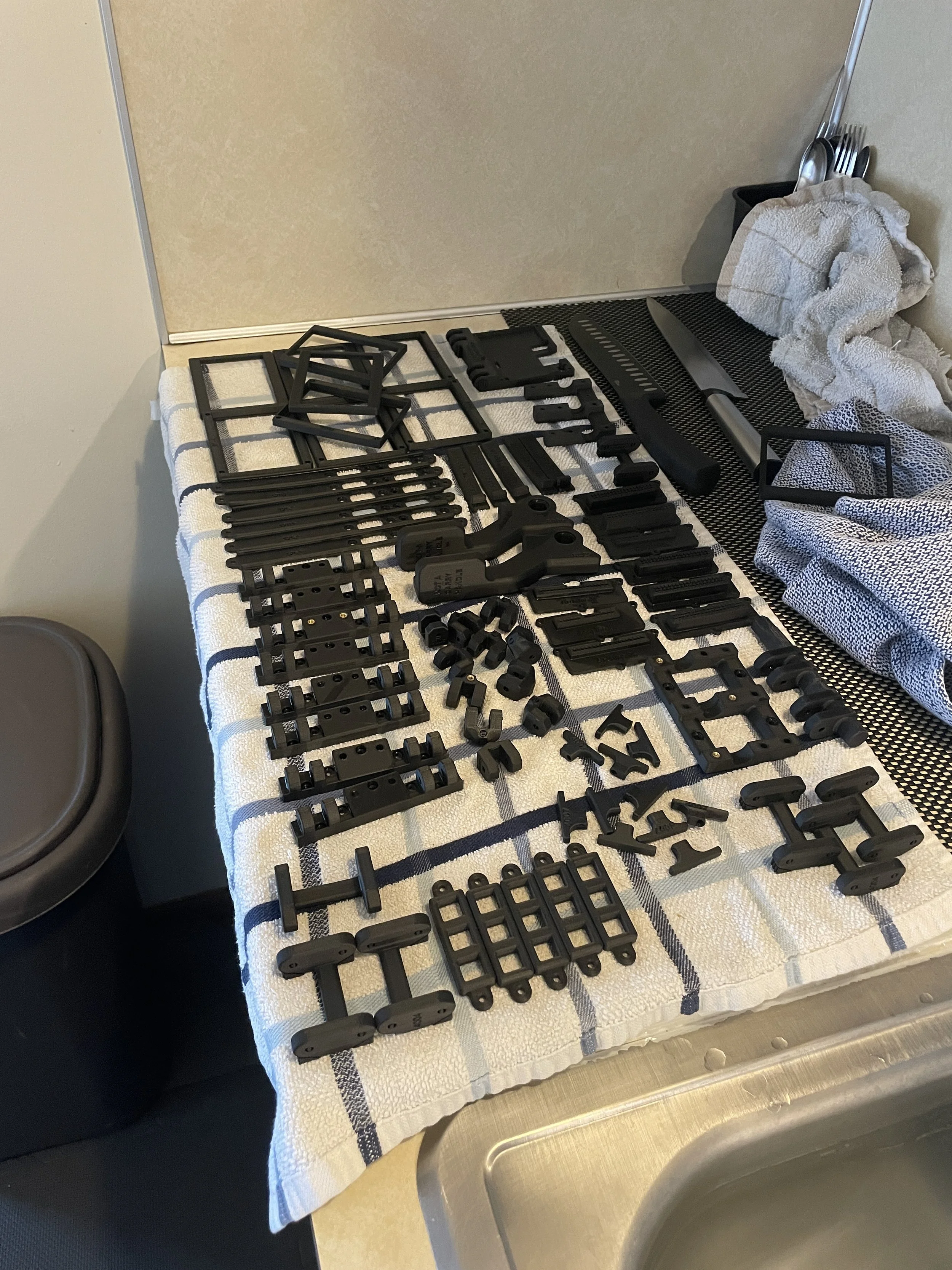
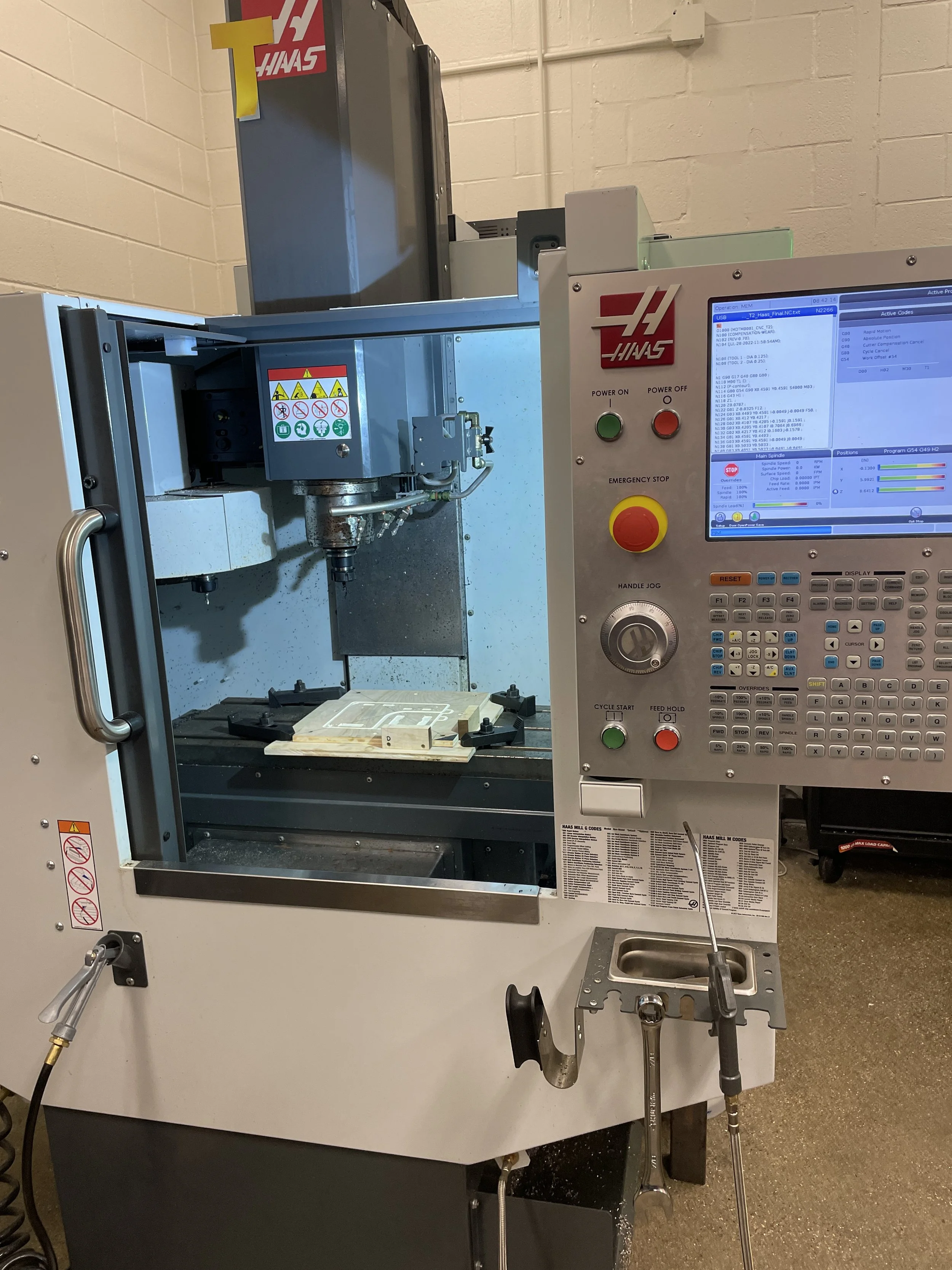
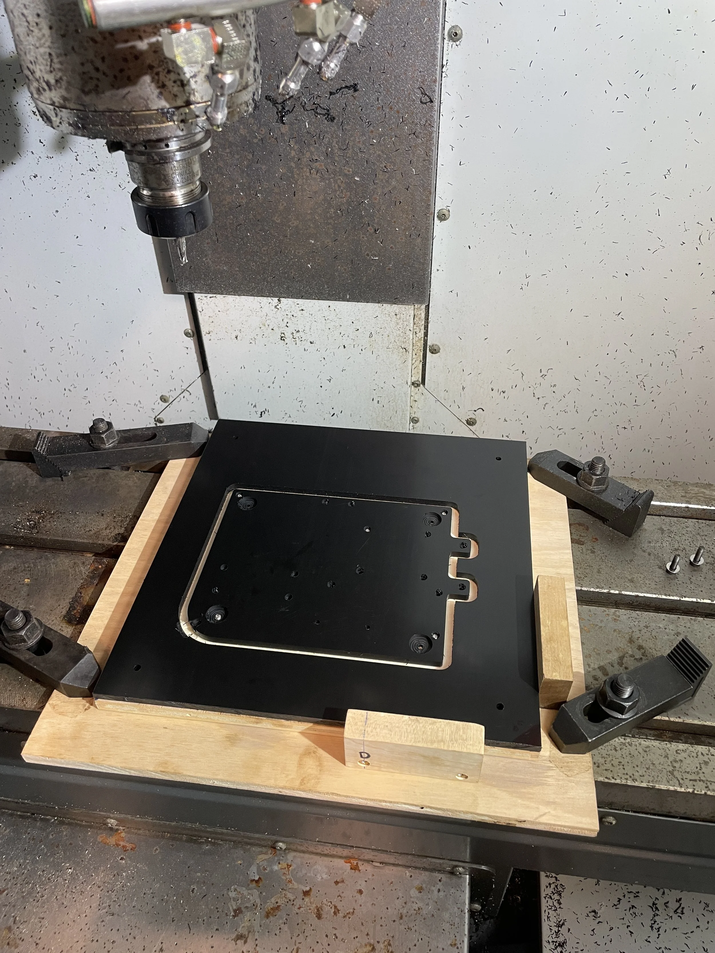
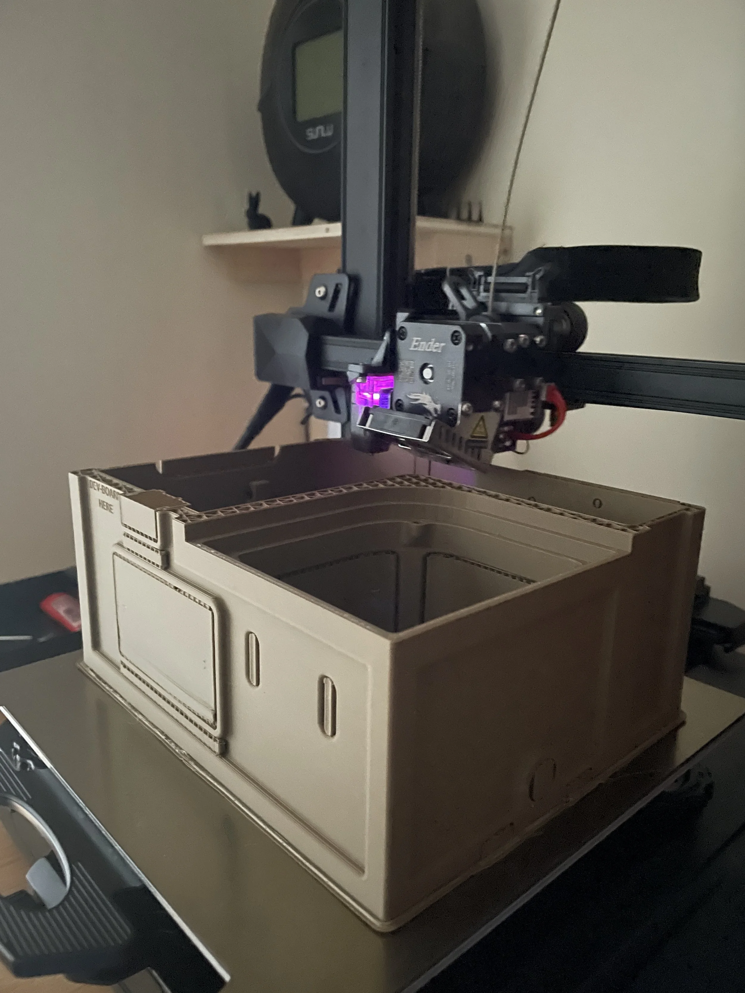
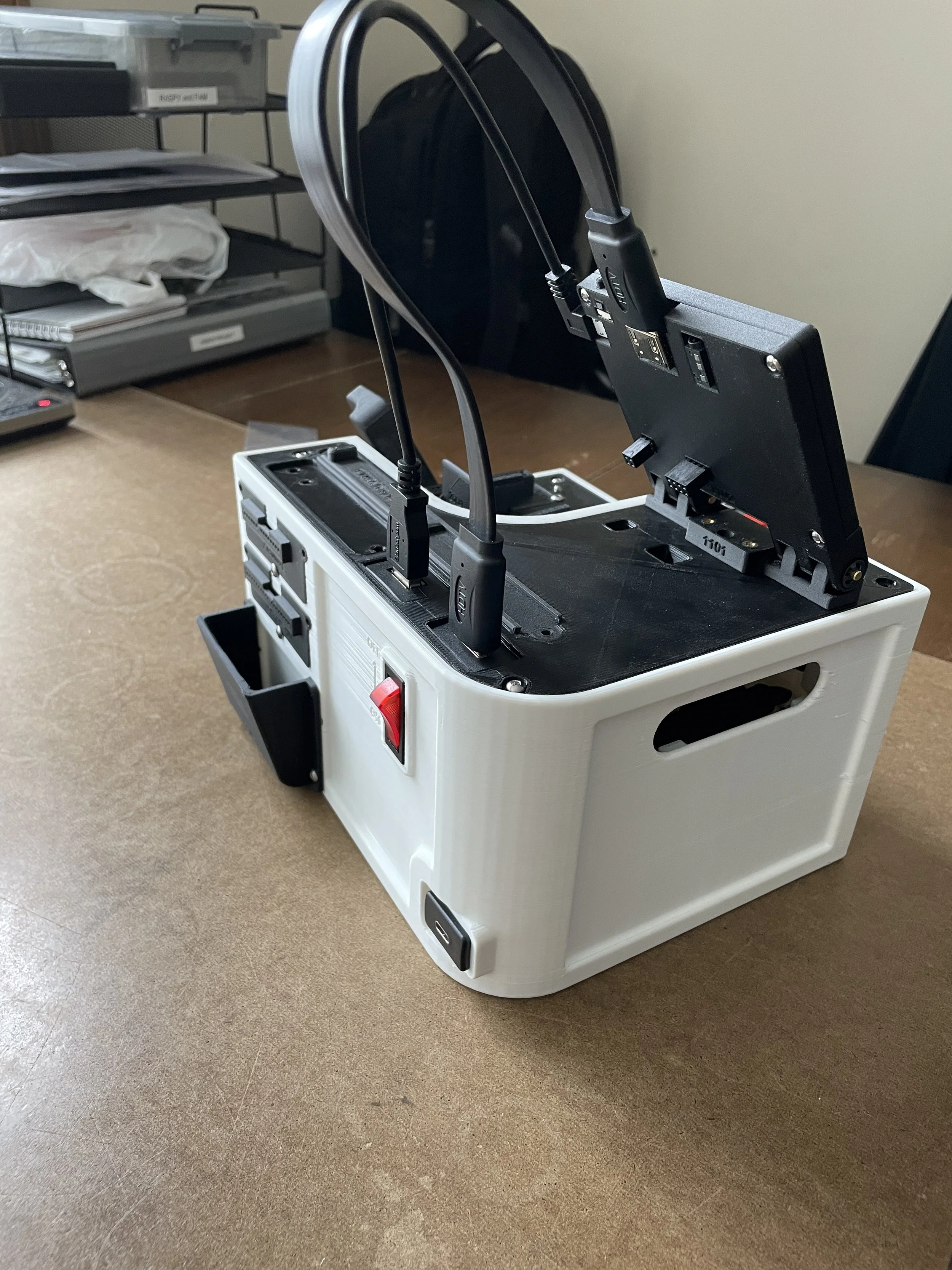
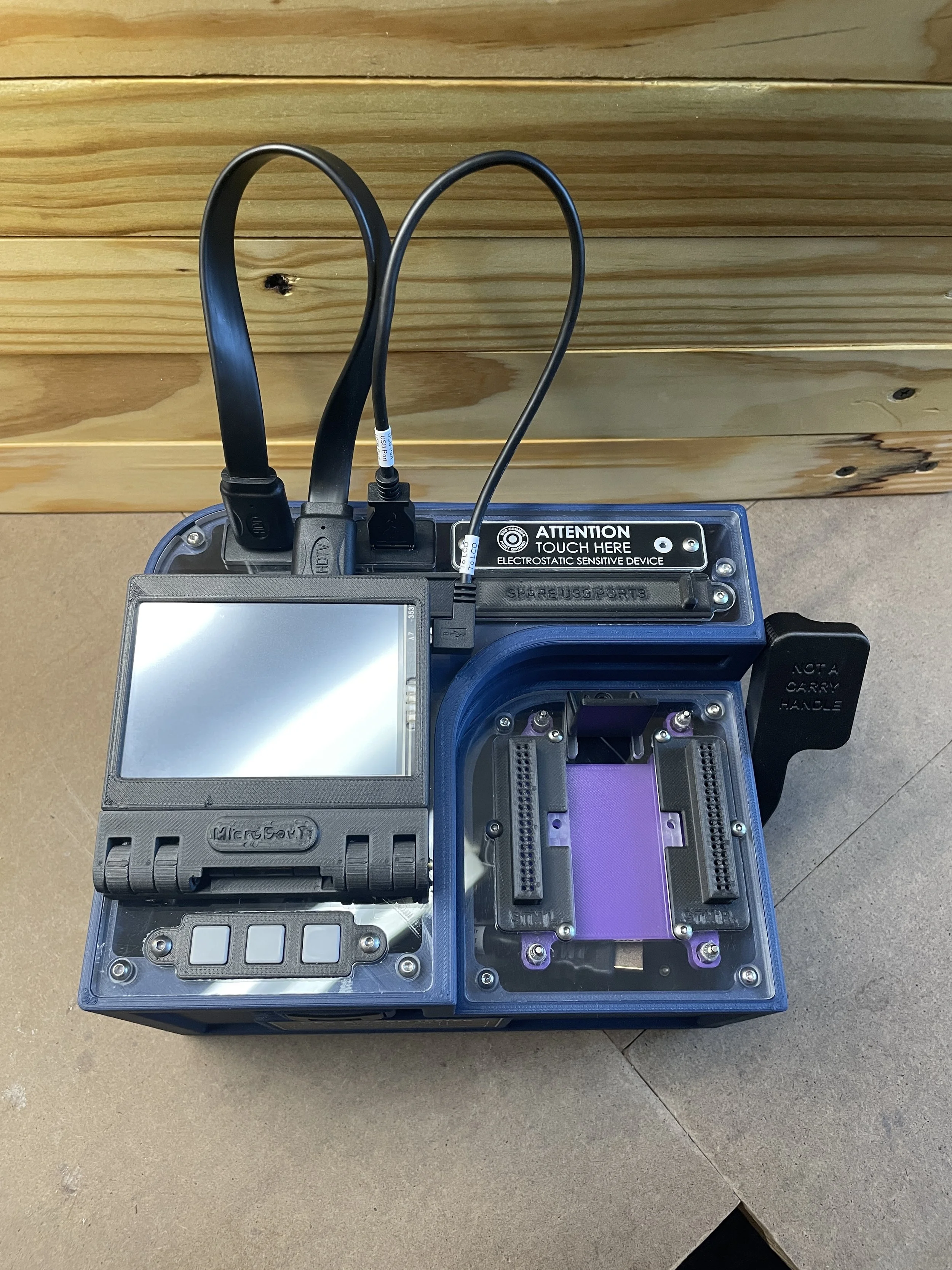
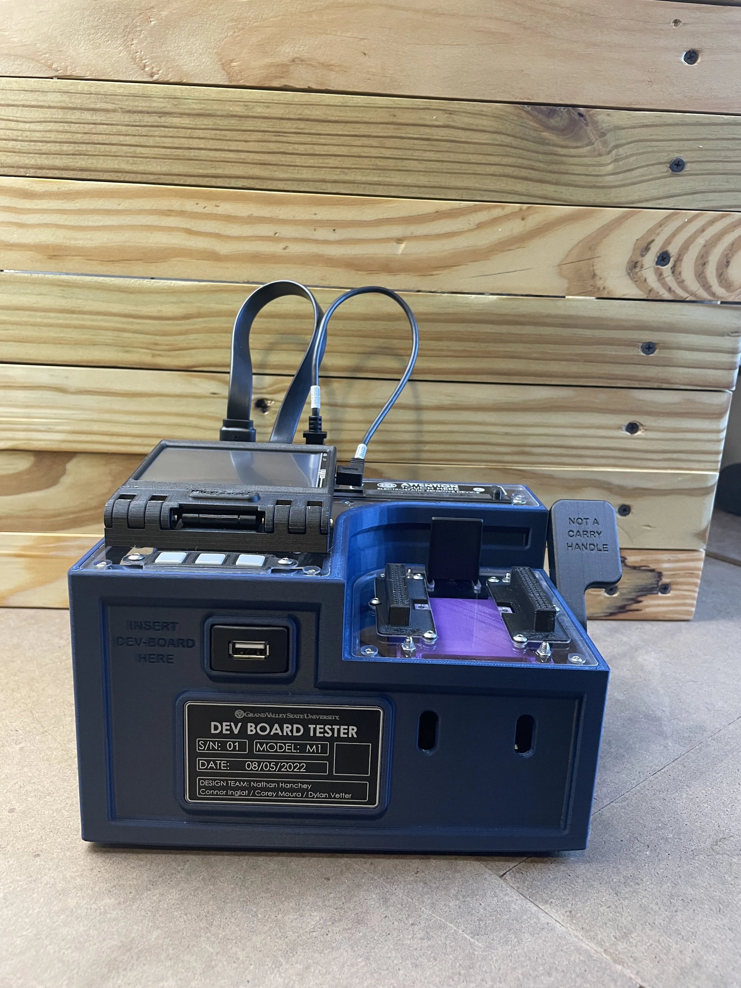
I designed and developed the device enclosure, which was manufactured using a combination of 3D printing (PLA and carbon fiber nylon) and CNC machining. The design incorporates a CNC-milled polycarbonate top and an ABS base to balance durability and manufacturability.
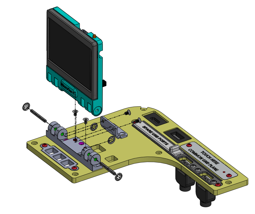
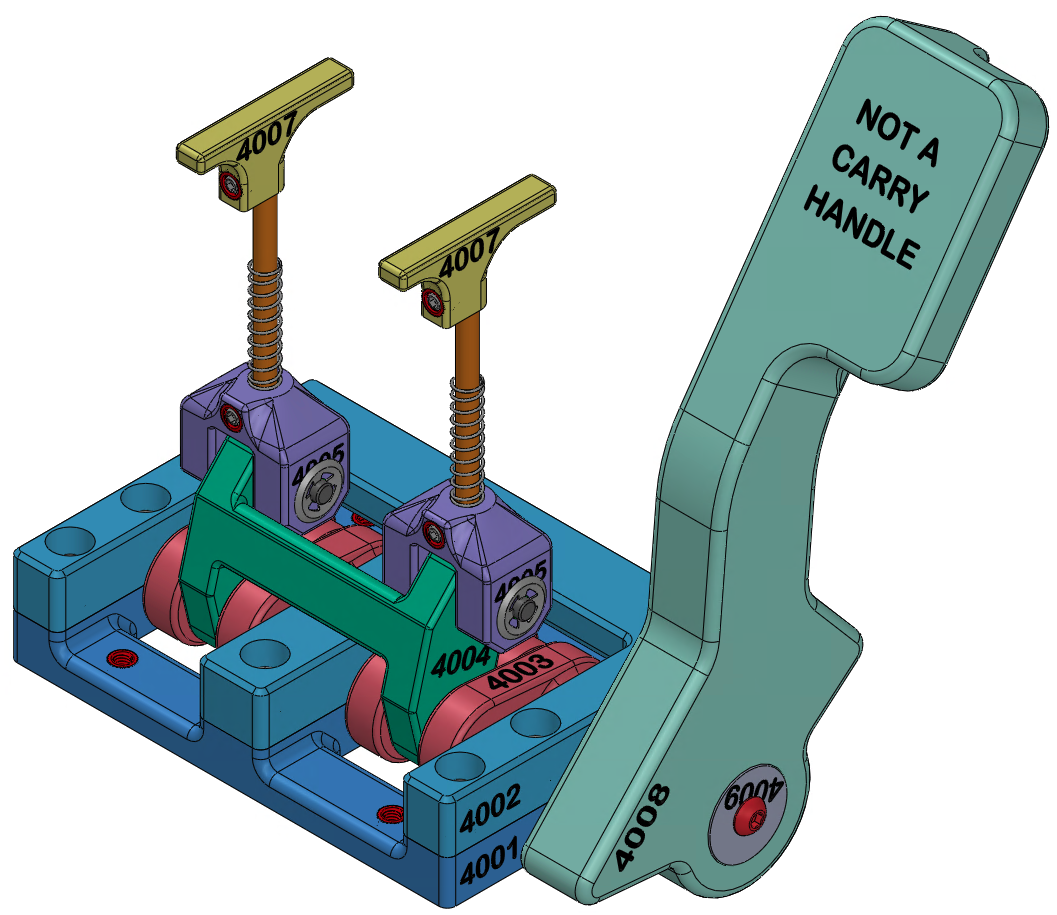
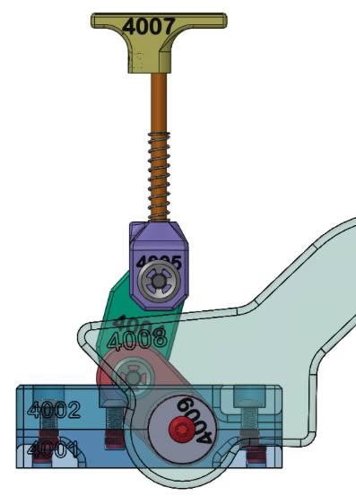
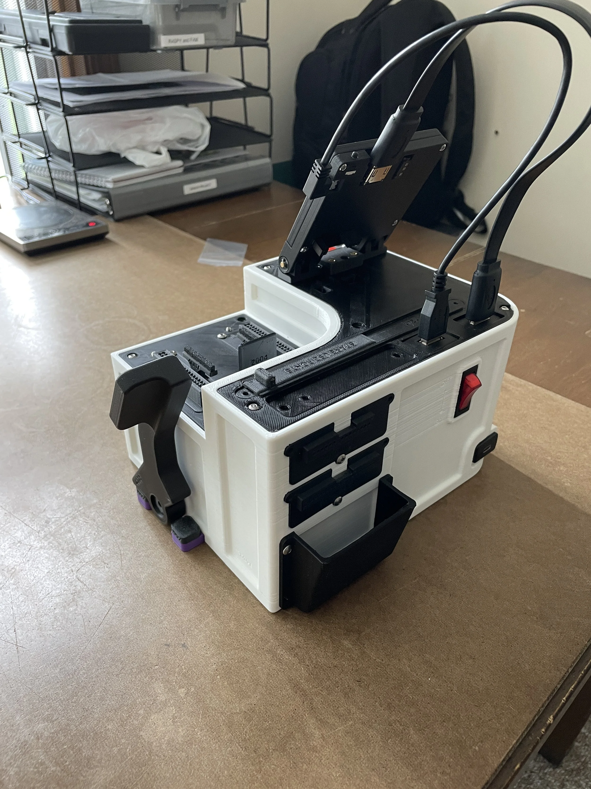
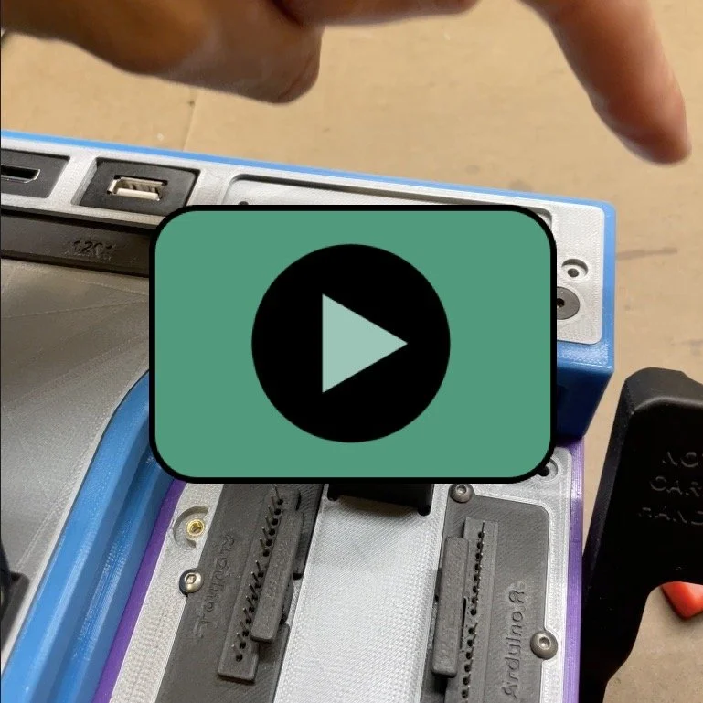
An integrated ejection mechanism enables safe removal of the subject board from the pin interface. The interface was designed to allow quick reconfiguration for compatibility with both Arduino Uno and STM32 microcontrollers.


Production Run
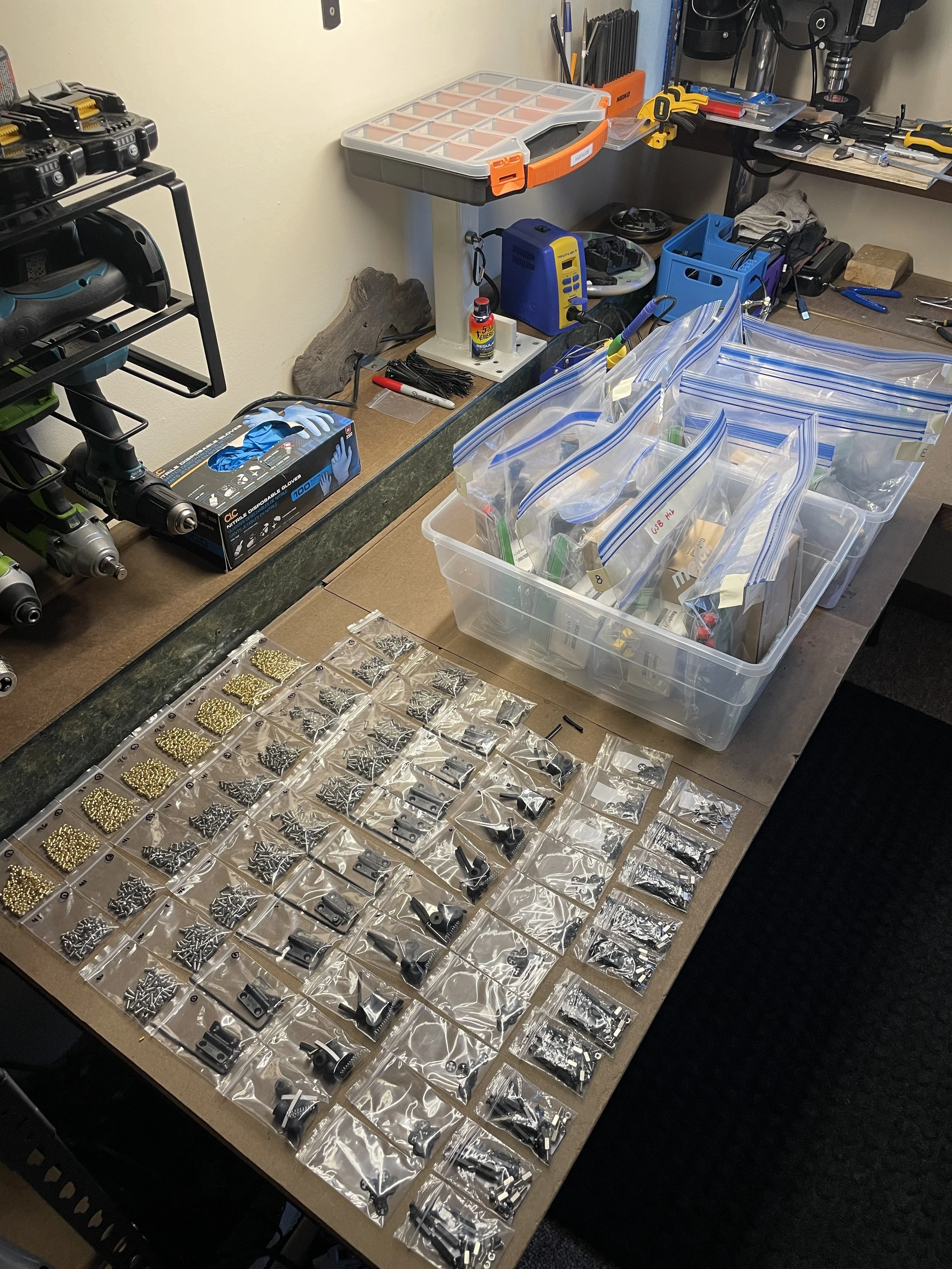
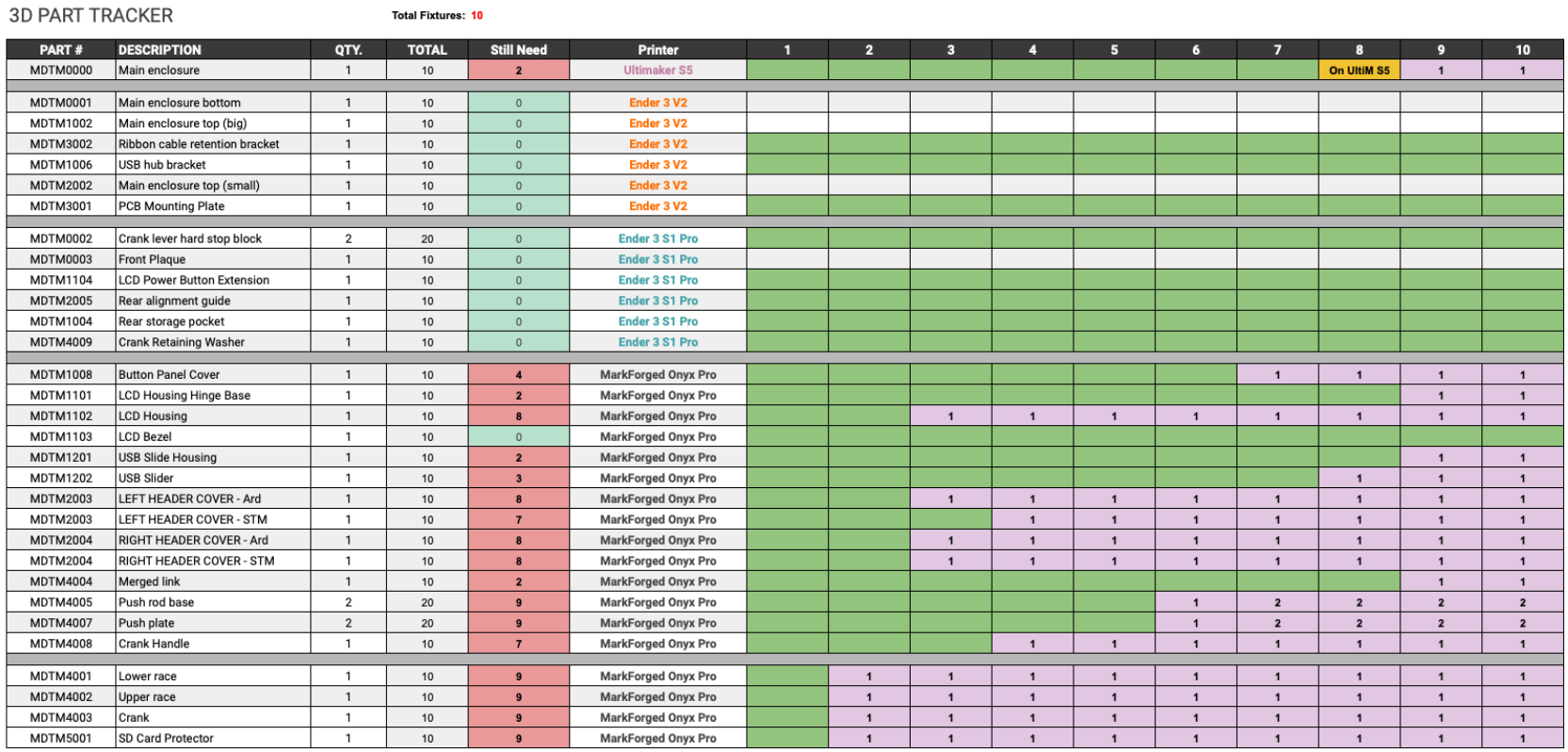
I led the production and assembly of all 10 devices, each consisting of approximately 60+ components including fasteners and heat-set inserts. This resulted in the coordination and assembly of over 600 individual parts across the full build.
To manage this process, I developed a part-tracking system in Excel to maintain organization, ensure accountability, and track progress throughout production.

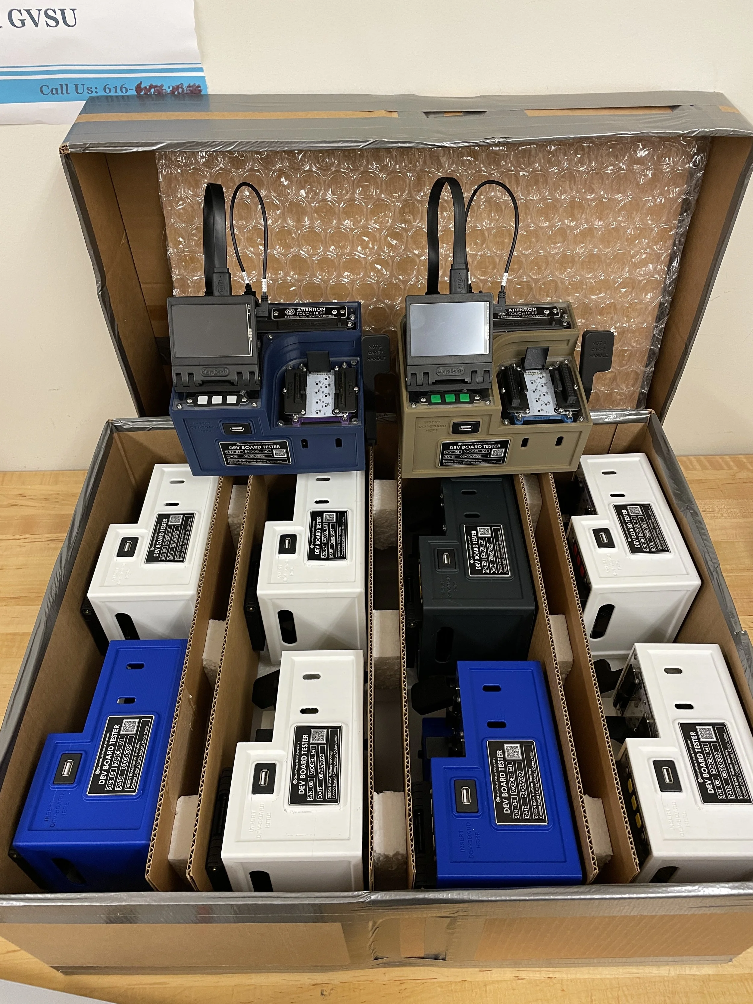


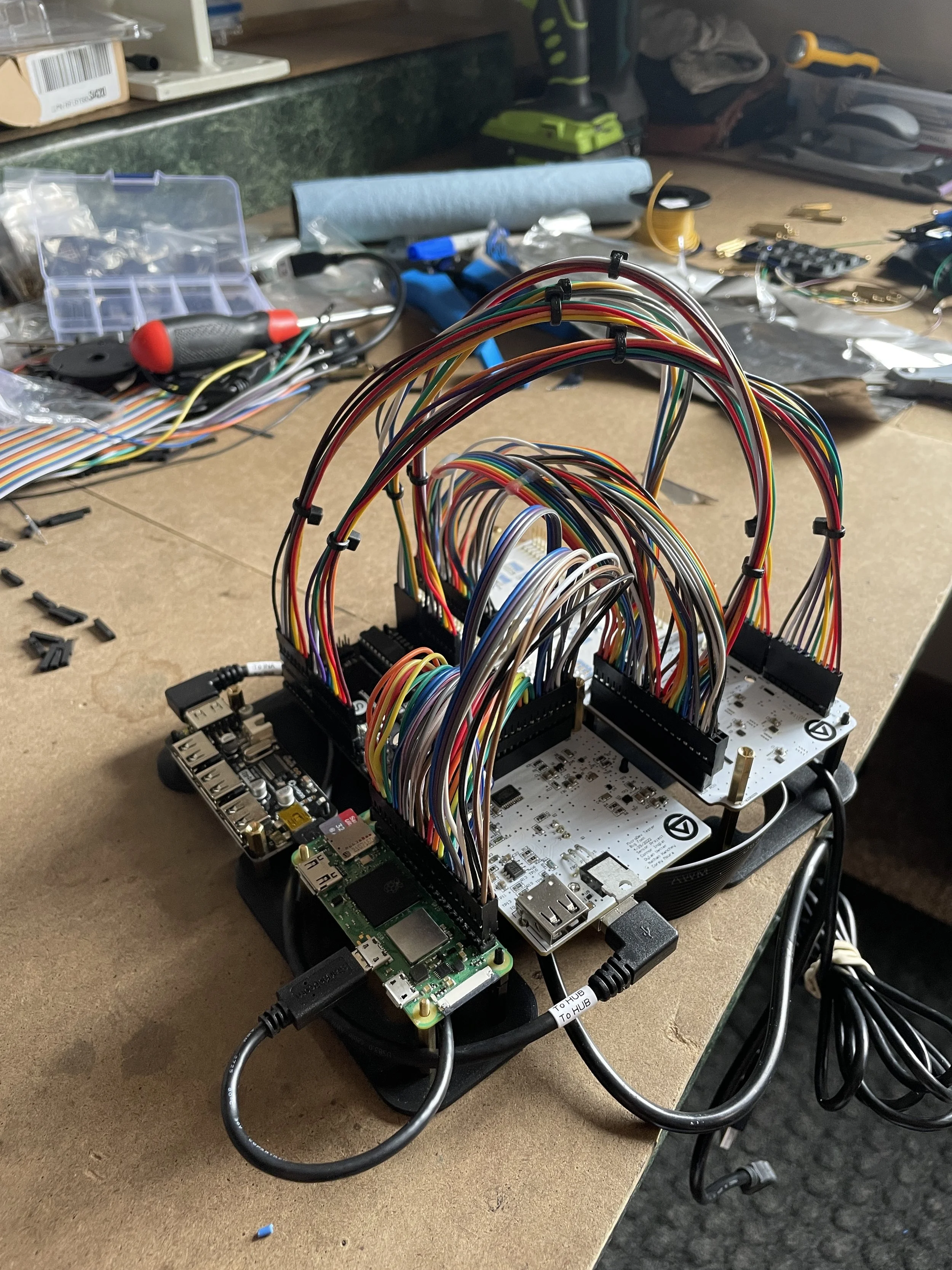
Results
All 10 units were tested and validated, including verification of all 20 PCBs (two per device). A shared Raspberry Pi was used during testing to confirm correct hardware functionality and interface behavior.
Each unit was made ready for deployment with the addition of a dedicated Raspberry Pi and software image. Full deployment was limited by Raspberry Pi availability during COVID-era global supply chain shortages.

Videos
Watch on YouTube
Short Demo
Laser Engraving
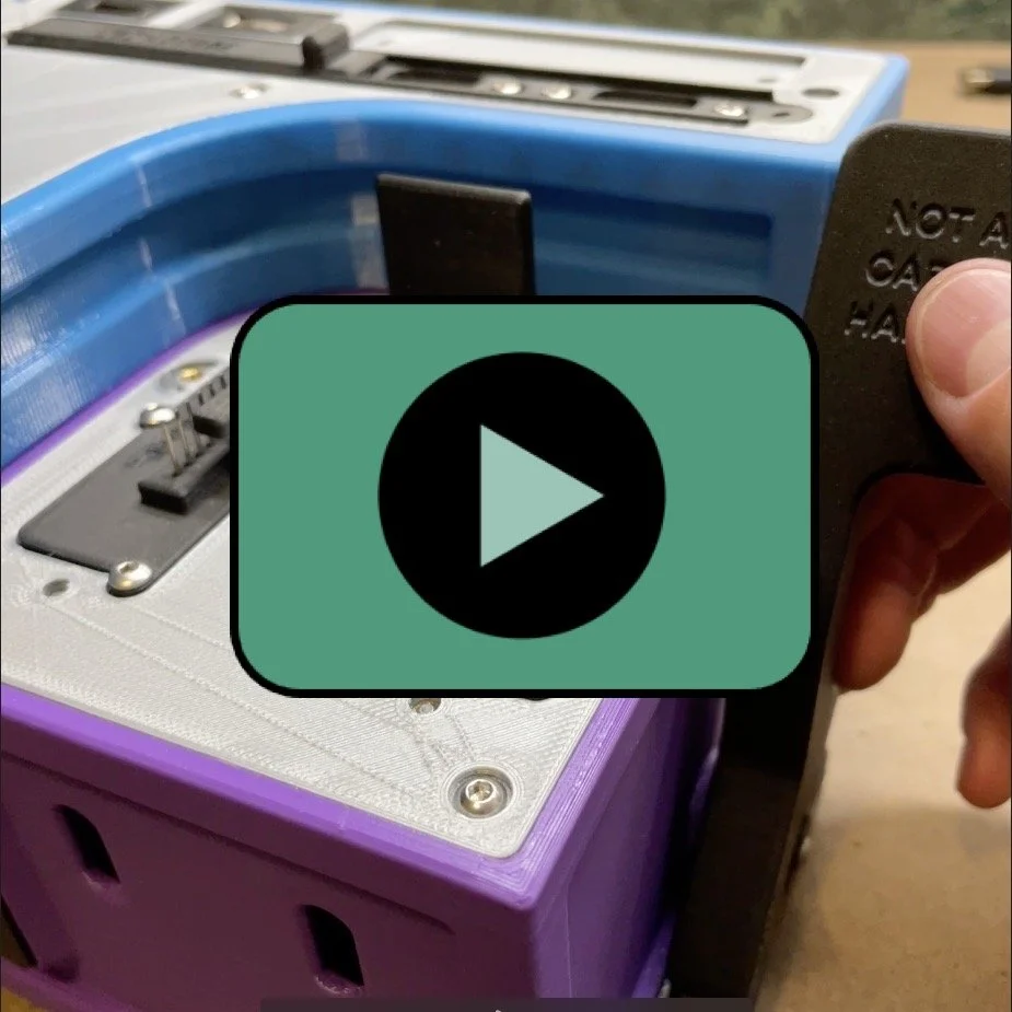
Ejection Assembly
USB-C Cover
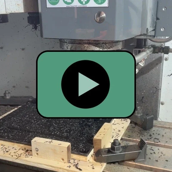
Machining ABS
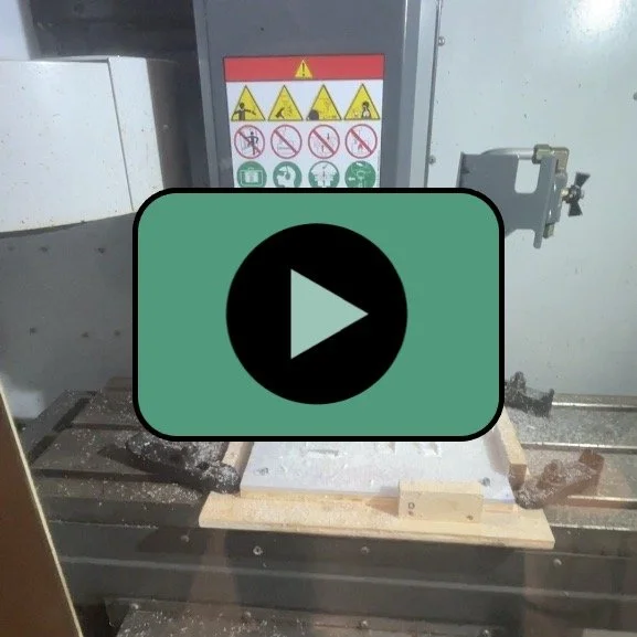
Machining Polycarbonate
Wiring Harnesses
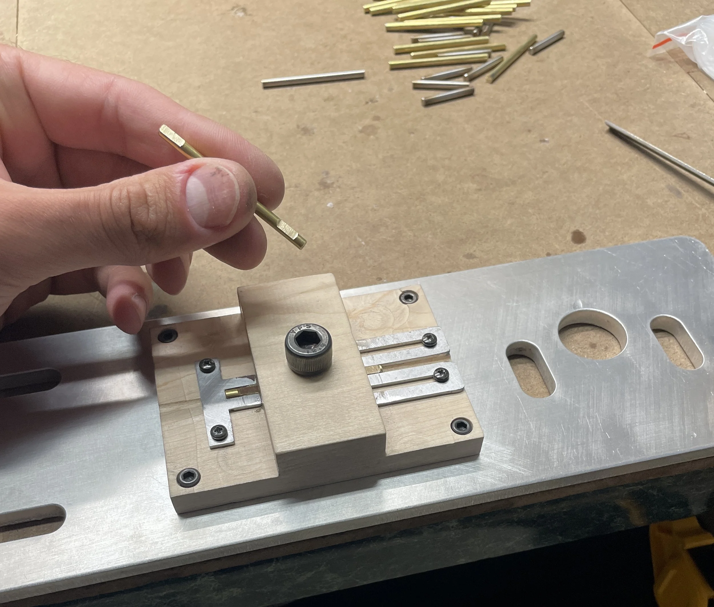
Parallel Flats