3-Link Suspension
March 2024 - April 2024

Overview
Following front-end frame damage, the suspension system was redesigned from a leaf spring solid axle setup to a custom 3-link configuration to improve ride quality, articulation, and overall performance.
The project involved full CAD modeling of the vehicle front section, suspension geometry development using a 3-link calculator, and custom bracket design to integrate coilovers, bump stops, and steering components within real-world packaging constraints.
-
The suspension system was redesigned from a leaf spring solid axle setup to a custom 3-link configuration to improve ride quality, articulation, and overall performance.
Suspension geometry was developed using a 3-link calculator to establish target link separation, link angles, and roll center behavior. These ideal conditions were then adapted to real-world constraints including frame geometry, ride height, drivetrain packaging, and steering linkage alignment.
Key design decisions focused on balancing on-road stability with off-road articulation, while maintaining proper steering behavior and minimizing unwanted effects such as bump steer and excessive load transfer through the link system.
-
Designed and modeled in SolidWorks
Custom 3-link solid axle suspension geometry
Geometry tuned to balance on-road stability and off-road articulation
Suspension travel: approximately 4 inches compression / 8 inches droop
Integrated Panhard bar for lateral axle control
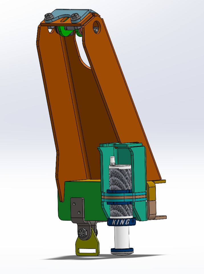
3-position upper link mount for adjustable anti-dive characteristics
King coilover shock towers with near-vertical orientation for efficient load transfer
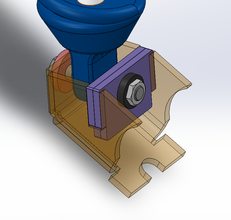
Adjustable bump stops and limit strap mounting provisions
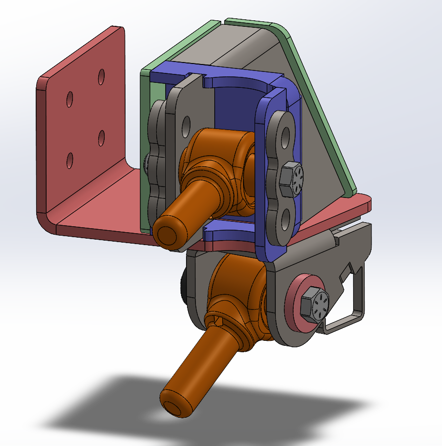
Full CAD modeling of suspension components including joints, brackets, and mounting interfaces
Designed with full articulation simulation to verify clearance and motion
Laser cut and press brake formed components
Relief cuts incorporated for multi-bend geometry and manufacturability
Brackets designed from 1/4 inch HRPO steel
Links constructed from 1.5 inch OD x 1/4 inch wall DOM tubing
Drainage and sealing considerations included for off-road durability
-
Challenges:
Translating ideal suspension geometry into a real-world vehicle required balancing performance targets with packaging constraints. Engine bay clearance, frame geometry, steering linkage, and ride height all limited component placement.
Fabrication constraints also required iteration, as certain bracket designs exceeded tooling limitations and had to be redesigned for manufacturability.
Outcomes:
The final design successfully integrates a complete 3-link suspension system within the existing vehicle architecture while maintaining proper articulation and component clearance.
This project strengthened my understanding of suspension kinematics, mechanical packaging, and designing for real-world fabrication processes.
Explore This Project
Suspension Geometry
A 3-link suspension calculator (vector-based graphical worksheet) was used to establish an idealized suspension geometry before translating the design into CAD.
Key parameters including link separation, link angles, anti-dive percentage, and roll center height were defined using the calculator. These values were then cross-referenced against the measured vehicle frame and adjusted to fit real-world packaging constraints while maintaining acceptable suspension behavior.
The final geometry was selected to balance on-road stability with off-road articulation. A moderate anti-dive value was targeted to reduce excessive front-end dive under braking, while maintaining compliance over uneven terrain. Roll center height was also tuned to promote predictable handling characteristics and minimize undesirable body roll behavior.
This geometry model served as the foundation for all subsequent CAD design, ensuring that link placement and mounting points were based on performance-driven targets rather than trial-and-error fabrication.

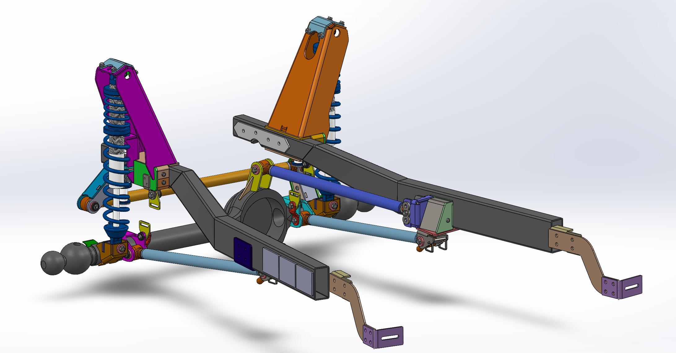
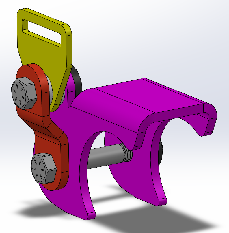
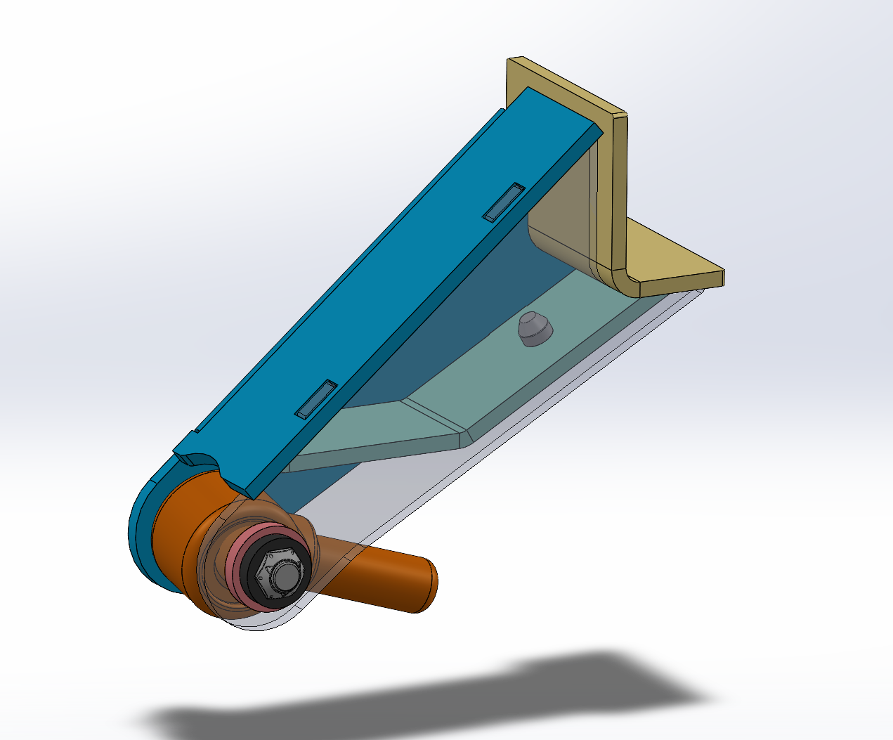
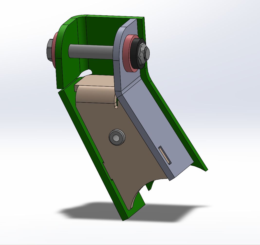
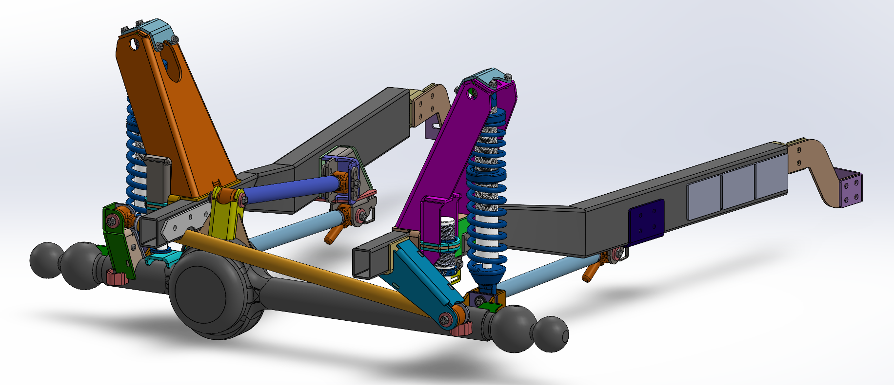
Mechanical Design (CAD)
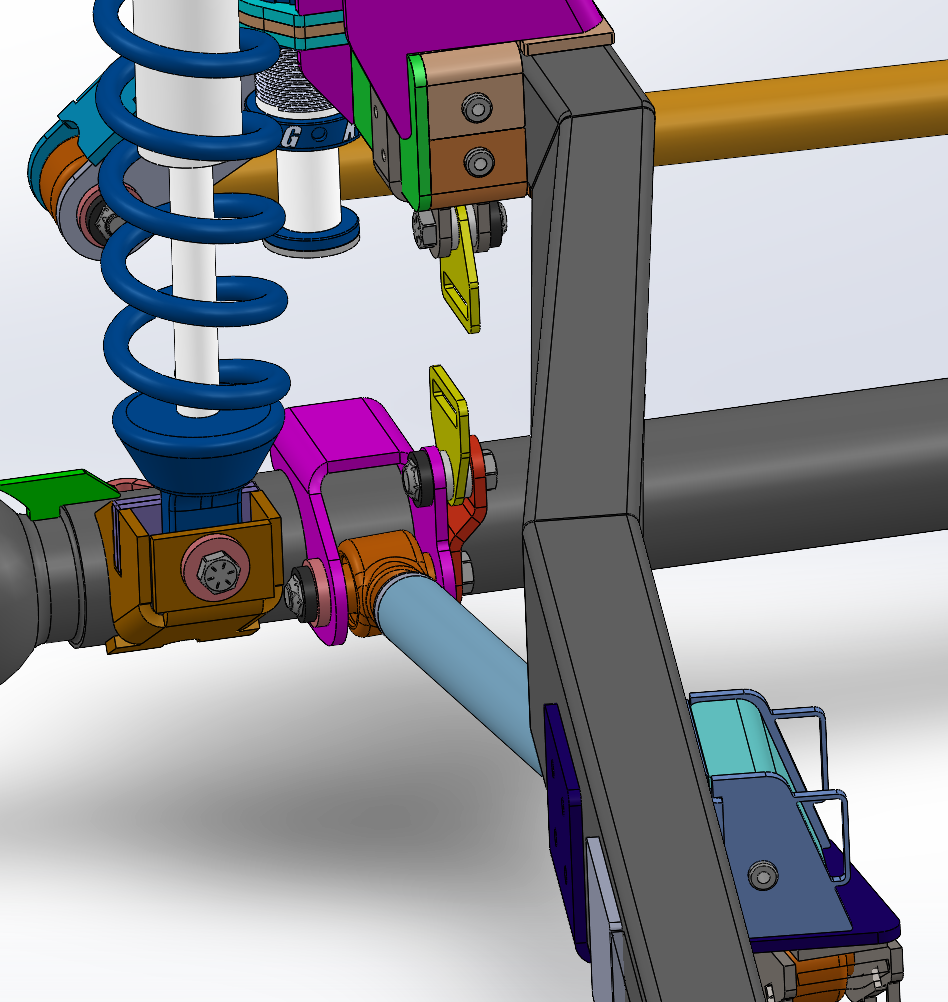
The suspension system was developed in SolidWorks to convert the target geometry into a fully defined and manufacturable design. A front frame section was recreated from physical measurements, allowing all mounting points and components to be positioned within real vehicle constraints.
All brackets and link mounts were designed and iterated in CAD to ensure proper fitment, alignment, and assembly. The system was articulated through full bump and droop travel to identify interference between components, including links, frame members, steering linkage, and coilovers.
Component placement was refined to maintain clearance throughout the full range of motion while accommodating engine bay packaging and steering geometry. Mounting interfaces were designed for reliable assembly, with attention given to bolt access, tolerancing, and alignment.
Bracket geometry and part design were developed with manufacturing in mind, including laser cutting and press brake forming constraints. Relief features and bend considerations were incorporated to ensure accurate fabrication and assembly.